
1w fm booster based 2n4427
The circuit operates on the principle of amplifying RF signals, making it suitable for applications in FM transmission. The use of two 2N4427 transistors in a push-pull configuration enhances the overall gain and efficiency of the amplifier. The transistors are capable of handling the power requirements while maintaining linearity, which is critical for FM signals to avoid distortion.
The design specifies a power supply of 12 Volts, with a recommended current rating of 500mA, ensuring that the circuit operates within safe limits. Exceeding the voltage beyond 15 Volts is cautioned against, as it can lead to thermal runaway and eventual failure of the transistors. The amplifier's gain of 15 dB is optimal for boosting signals in the specified frequency range, which is particularly useful for FM broadcasting applications.
The inductors L4, L5, and L6 play a crucial role in tuning the amplifier to the desired frequency range. These air-core coils, constructed with 1mm wire, provide the necessary inductance while minimizing losses associated with core materials. The choice of 8 turns for each coil is a balance between size and inductance, ensuring compactness without compromising performance.
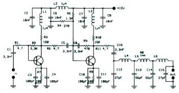
This circuit can be assembled on a standard PCB, with attention to layout to minimize parasitic inductance and capacitance. Proper grounding techniques and decoupling capacitors are recommended to ensure stable operation. Overall, this FM booster circuit is an effective solution for enhancing the range and clarity of FM transmission, making it a valuable project for electronics enthusiasts and professionals alike.This is the circuit diagram of linear FM Booster / RF amplifier based 2N4427 Philips transistor. The RF Amplifier is for boosting small fm transmitters and bugs. It use two Philips 2N4427 and its power is about 1Watt. At the output you can drive any linear with BGY133 or BLY87 and so on. Its power supply has to give 500mA current at 12 Volts. More voltage can boost the distance but the transistors will be burned much earlier than usual. ! In any case do not exceed the 15Volts. The Amp offers 15 dB in the area of 80Mhz to 110 Mhz. L4, L5, and L6 are 5mm diameter air coils, 8 turns, with wire 1mm wire diameter. This is an easy project, but will give you great results. 🔗 External reference
Related Circuits
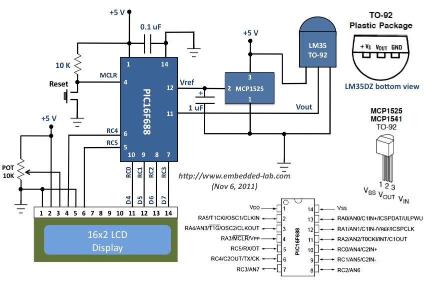
This document outlines a revised version of an LM35-based digital thermometer project previously shared. While it is a straightforward project, it remains popular among beginners learning about microcontrollers. The initial version contained a flaw, as some readers noted that...
The following circuit illustrates a Bass and Treble Controller Circuit. This circuit is constructed based on the classic Baxandall tone control circuitry. The Bass and Treble Controller Circuit is designed to adjust the low and high-frequency response of audio signals,...
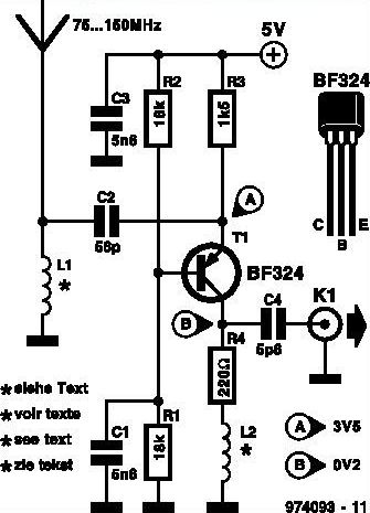
This inexpensive FM radio receiver antenna booster utilizes the BF324 TO92 style PNP transistor in a grounded-base configuration. The circuit can be employed as a... The FM radio receiver antenna booster circuit is designed to enhance the reception capabilities of...
The following circuit illustrates a Repeating Interval Timer Circuit Diagram. This circuit is based on the CMOS 4060 integrated circuit (IC). Features include a 6-pin output. The Repeating Interval Timer Circuit utilizing the CMOS 4060 IC is designed to generate...
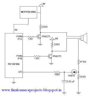
A horn driver project developed by Microchip Technology is illustrated in this circuit diagram. This horn driver project utilizes the PIC16F886 microcontroller from Microchip. The circuit diagram for the PIC microcontroller horn driver is straightforward and requires minimal external...
If a page name is not selected by pressing the button, the previously selected page name continues to be used. The value is stored in EEPROM and may be changed at any time. When the unit is first powered...
Warning: include(partials/cookie-banner.php): Failed to open stream: Permission denied in /var/www/html/nextgr/view-circuit.php on line 713
Warning: include(): Failed opening 'partials/cookie-banner.php' for inclusion (include_path='.:/usr/share/php') in /var/www/html/nextgr/view-circuit.php on line 713