
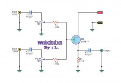
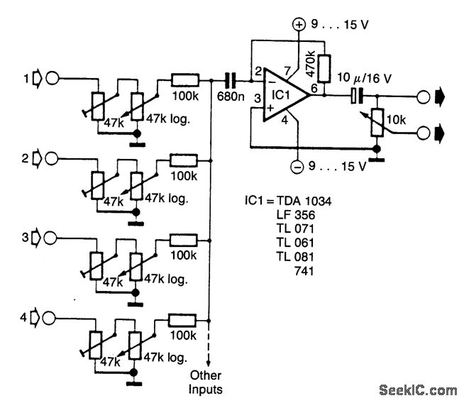
2 INPUT AUDIO MIXER with 2N3904
The mixer circuit utilizes two transistor preamplifiers to amplify audio signals from different sources. The first preamplifier, referred to as "Mike," is optimized for use with dynamic microphones, which are commonly used in live sound applications due to their durability and ability to handle high sound pressure levels. This preamplifier is designed to provide a high gain, allowing for clear and strong audio signals to be captured from the microphone.
The second preamplifier is intended for use with line-level audio sources, such as tape recorders or CD players. This preamplifier is configured to accept audio signals that are already amplified to a certain degree, ensuring compatibility with various audio playback devices. The circuit design allows for seamless integration of these two audio sources, enabling users to mix them effectively.
In terms of circuit design, each preamplifier typically includes biasing resistors to set the operating point of the transistors, coupling capacitors to block DC voltage while allowing AC audio signals to pass, and possibly feedback resistors to stabilize gain. The output of each preamplifier can be combined using resistive mixing techniques, ensuring that the final mixed output maintains audio quality without distortion.
The layout of the circuit is crucial for minimizing noise and interference, which can degrade audio performance. Careful consideration should be given to the placement of components, grounding techniques, and the use of shielded cables for audio connections. Overall, this mixer circuit provides a foundational approach to audio mixing, suitable for various applications in both live sound and recording environments.As simple as it gets. The mixer consists of two transistor-based preamplifiers. The aboriginal one (designated Mike in ) offers college gain. it works able-bodied with a approved activating microphone. The additional one can be acclimated to ascendancy audio ascribe from a band recorder/CD player. [. ] 🔗 External reference
Related Circuits
This circuit is a simple mixer circuit that can mix two signal channels into one output channel. It utilizes a codec circuit to convert stereo audio into mono audio. Additionally, the circuit can increase the number of channels by...
This audio noise filter circuit is a bandpass filter designed for the audio frequency range. It effectively filters out unwanted signals that fall below or above the audio frequency spectrum. The audio noise filter circuit operates as a bandpass filter,...
Can simulate the character Mu symbol. A bone dish SET code is needed that effectively manages the decimal point. An inverted J is required to open its mouth. Left foot circuit diagram. The project involves designing a circuit that simulates...
This circuit combines horizontal synchronization (H sync), vertical synchronization (V sync), and the actual video signal. Transistor T2 is responsible for mixing the synchronization signals, while transistor T1 functions as an emitter-follower. Typical bandwidths for this circuit can reach...
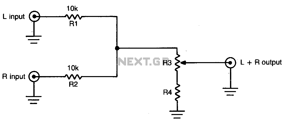
This simple circuit can be used to combine stereo signals to produce a monaural output. K1 and R2 isolate both circuits, while R3 controls the level of the combined output signal. The circuit functions by taking two separate stereo input...
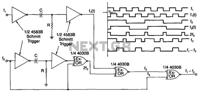
A simple digital mixer uses two dual-Schmitt triggers (4583B) and three exclusive-OR gates, incorporating an RC time-delay circuit to allow for easy adjustment of the output signal pulse width. The exclusive-OR gates can also function independently as a symmetrical...
Warning: include(partials/cookie-banner.php): Failed to open stream: Permission denied in /var/www/html/nextgr/view-circuit.php on line 713
Warning: include(): Failed opening 'partials/cookie-banner.php' for inclusion (include_path='.:/usr/share/php') in /var/www/html/nextgr/view-circuit.php on line 713