
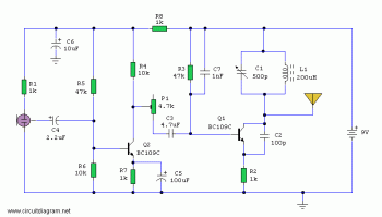
50 Khz center frequency optical transmitter
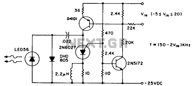
The described circuit operates on a modulation scheme that allows for pulse repetition rates to remain stable across varying environmental conditions. The modulation voltage, V1N, plays a critical role in determining the frequency of the emitted pulses, ensuring that the system can maintain consistent communication even when external factors fluctuate.
The use of an infrared emitting diode (IRED) such as the F5D1 is essential for extending the operational range of the transmitter. This component is designed to emit infrared light at a wavelength that is optimal for detection by phototransistors like the L14P2. The selection of these components should consider their spectral characteristics to ensure that the emitted light is effectively captured by the phototransistor.
In terms of power efficiency, maintaining an average consumption of less than 3 watts is significant for battery-operated or low-power applications. This low power consumption allows for prolonged operational periods without the need for frequent recharging or battery replacement, making the system suitable for remote or portable applications.
To further enhance the system's performance, the integration of lenses or reflectors at both the emitter and detector is recommended. These optical elements can focus the emitted infrared light, increasing the intensity of the signal that reaches the phototransistor. Additionally, they can help to mitigate the effects of ambient light interference, which can adversely affect the system's performance by introducing noise into the received signal. By optimizing the optical path, the overall efficiency and reliability of the communication system can be significantly improved.
In summary, this circuit design emphasizes the importance of component selection, power efficiency, and optical enhancements to achieve effective and reliable information transfer over extended distances in various environmental conditions.The pulse repetition rate is relatively insensitive to temperature, and power supply voltage and is a linear function of V1N, the modulating voltage. Useful information transfer was obtained in free air ranges of 12 feet (~ 4m). Greater range can also be obtained by using a higher power output IRED such as the F5D1 in combination with the L14P2 phototransistor.
Average power consumption of the transmitter circuit is less than"3 watts. Lenses or reflectors at the light emitter and detector increases range and minimizes stray light noise effects. 🔗 External reference
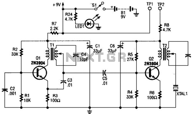
Related Circuits
The transmitter features a VXO circuit that drives a keyed amplifier. This keyed amplifier powers an MRF 476 final amplifier, producing approximately 2 watts of output. Additionally, a solid-state T-R switch is incorporated for the receiver. The component values...
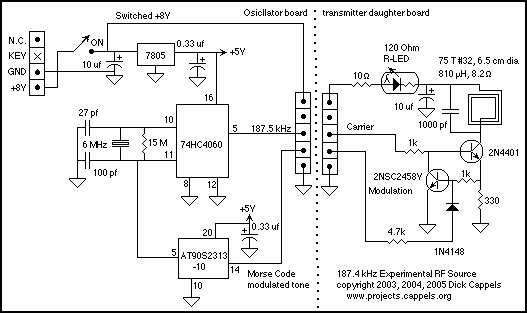
An oscillator, a small power stage, some modulation, and a tiny loop antenna make RF for experiments on at 187.5 kHz on the United States' FCC Part 15 Lowfer band (1600-1750 meters). This is a low power signal source...
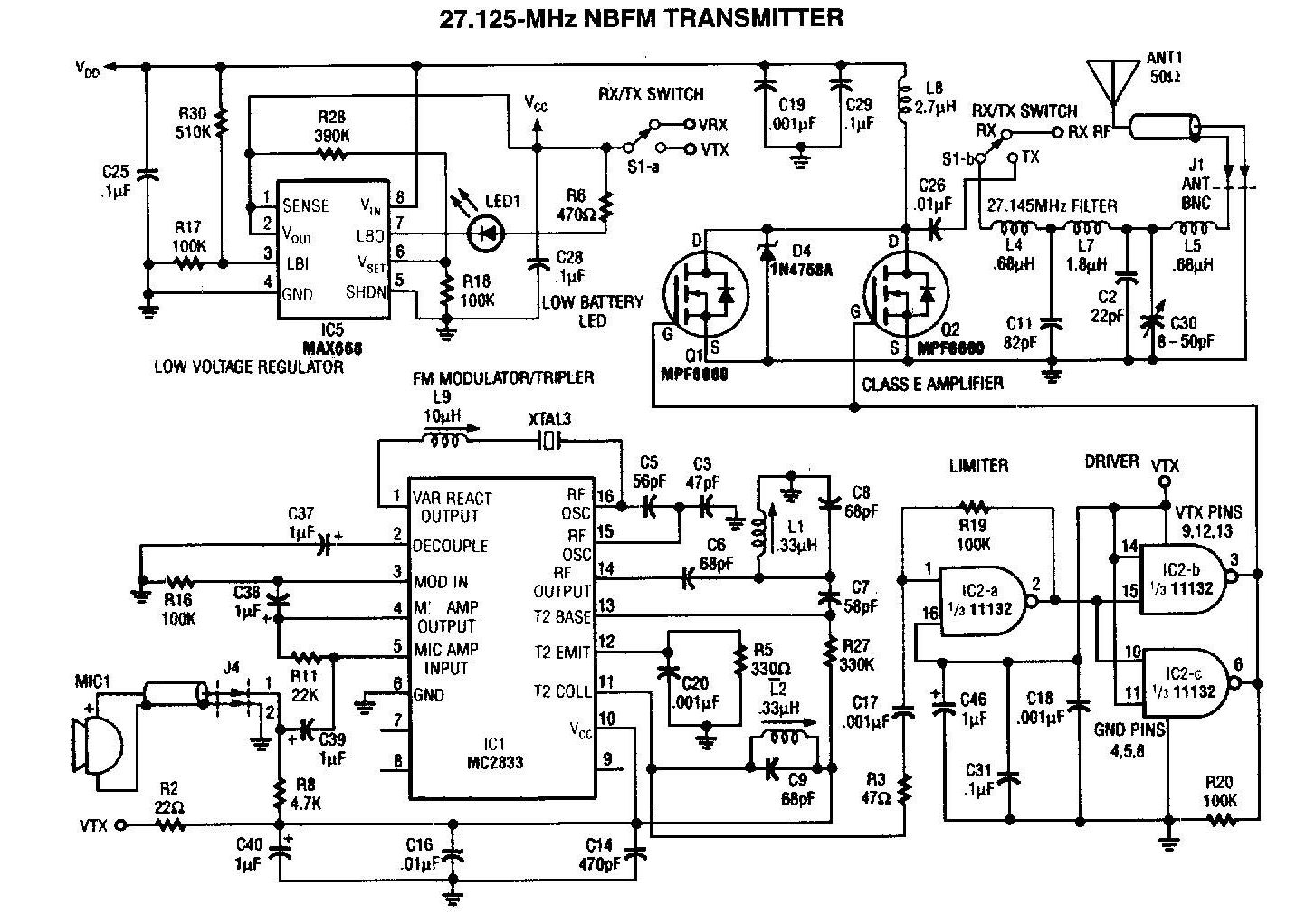
A 27MHz transmitter circuit schematic utilizing the MC2833 and two FET transistors, MPF6660. This design incorporates a Motorola MC2833 one-chip FM transmitter along with several supporting components. The 27MHz transmitter circuit is designed to operate within the FM radio frequency...
The following diagram is the schematic diagram of a four-transistor FM transmitter circuit designed by Paul K. Sherby. Components List: R1, R2, R8 = 1K, R3 = 100K, R4 = 150K, R5, R7 = 10K, R6 = 220 ohm,...

The divider design is straightforward. Users can select a division factor of 1, 10, or 100, or opt for no output (tied low) through the CONTROL input connected to the analog multiplexer HC4052. The design utilizes AC04 to drive...
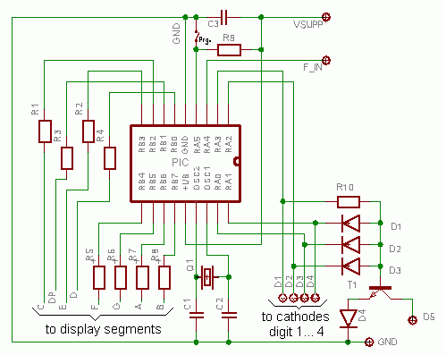
This document outlines the construction of a compact frequency counter utilizing an inexpensive PIC microcontroller and several seven-segment LED displays. A PIC programmer necessary for programming the PIC 16F628 is accessible on DL4YHF's website. Requests for programmed PICs or...