
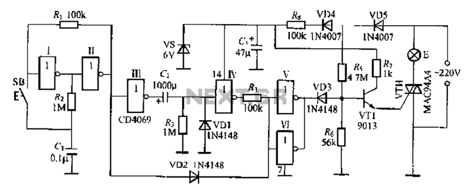
220V AC Lamp Touch Dimmer

The 220V AC lamp touch dimmer circuit utilizes a touch-sensitive mechanism to control the brightness of incandescent lamps. The core component of this circuit is the 8-pin CMOS IC, such as the TT8486A or TT6061A, which is responsible for processing the touch input and controlling the output to the lamp.
The operation of the circuit begins when a user touches the designated area of the dimmer. This touch is detected by the IC, which then activates a series of internal processes to adjust the brightness of the connected lamp. The circuit typically features three distinct brightness levels, allowing users to cycle through them with each touch. The IC manages the switching of the lamp's power through a triac or a similar component, ensuring smooth transitions between the brightness levels.
The design of the circuit incorporates necessary safety features to handle the high voltage AC supply. Components such as resistors, capacitors, and protective diodes are included to stabilize the operation and protect against voltage spikes. Additionally, the layout of the circuit should ensure that the touch sensor is properly isolated from high voltage areas to prevent accidental electric shocks.
In summary, the 220V AC lamp touch dimmer circuit provides a user-friendly interface for adjusting lamp brightness through a simple touch, leveraging the capabilities of an 8-pin CMOS IC to achieve efficient and safe operation.Here the 220V AC lamp touch dimmer circuit. By only touching this touch dimmer you are able to increase the light intensity of incandescent lamps in three stages. The touch dimmer is designed all around 8-pin CMOS IC TT8486A/TT6061A especia.. 🔗 External reference
Related Circuits
A delay lamp circuit is ideal for bedside tables, featuring a button (SB) that turns the light on and off. If the button is not pressed, the circuit maintains a delay before the light turns off. If the light...

A project is underway to create a custom electronic circuit for a 1969 Chevelle. The design aims to replicate a retained accessory power feature similar to a product offered by Dakota Digital, but at a lower cost. The circuit...
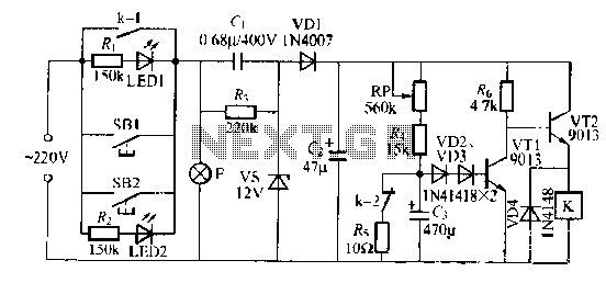
The lamp relay delay circuit is illustrated in Figure 7. Components S131 and SB2 are light buttons mounted in different locations. The lamp can operate with F. LEDs (LED1 and LED2) should be installed in SB1 and SB2 to...

This circuit for a powerful flashing lamp is suitable for use in vehicles. The LM395 integrated circuit, also known as a super-transistor, is a highly robust monolithic power transistor that includes features such as thermal protection and current limiting....
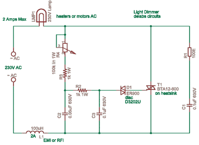
A dimmer is a simple device used to reduce the brightness of incandescent lamps and to control the speed of collector motors. This concept has gained popularity due to the abundance of outdated Soviet circuits available on Lithuanian internet...

The Zener diode provides a constant voltage of 20 V to the unijunction transistor Q1, except at the end of each half-cycle of the input when the line voltage drops to zero. Initially, the voltage across capacitor C1 is...
Warning: include(partials/cookie-banner.php): Failed to open stream: Permission denied in /var/www/html/nextgr/view-circuit.php on line 713
Warning: include(): Failed opening 'partials/cookie-banner.php' for inclusion (include_path='.:/usr/share/php') in /var/www/html/nextgr/view-circuit.php on line 713