
Zero voltage switch temperature control
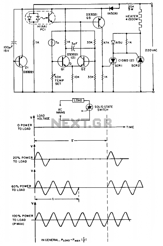
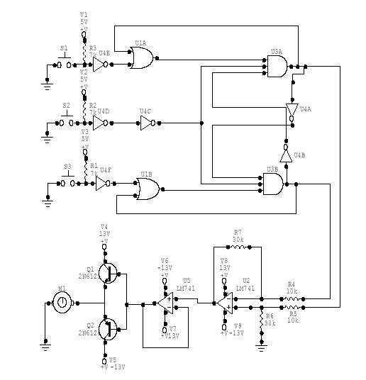
The circuit overcomes the latching issue by using a pair of highly sensitive low current reverse blocking thyristors (C106) arranged in antiparallel. These thyristors are triggered by a simple thermistor-modulated differential amplifier (Q1, Q2), with zero voltage logic provided by an H11AA1 AC input optocoupler. When the NTC thermistor (TH) calls for heat, transistor Q1 is turned off, and Q2 is activated, which typically supplies continuous base drive to transistor Q3, leading to the triggering of either SCR1 or SCR2 depending on the AC input phasing. When the AC input voltage is positive relative to SCR2, SCR1 is reverse biased, and with gate current from Q3, it acts as a remote base transistor, outputting positive gate trigger current for SCR2 via blocking diode CR1. Conversely, when the AC input polarity reverses (with SCR1's anode positive), SCR1 functions as a directly fired conventional thyristor. However, the trigger current to SCR1 is not continuous, even while TH is demanding heat and Q2 is providing base current to Q3. In this scenario, Q3 is prevented from conducting by the clamping action of PCI, an H11AA photocoupler, except during brief moments when the AC input voltage approaches zero, resulting in the coupler input diodes being current-deprived. Triggering of either SCR can only happen at AC voltage crossing points, which ensures RFI-less operation. The proportional control feature is integrated through the positive feedback action of capacitor CM, transforming the differential amplifier (Q1, Q2) into a simple multivibrator, with a duty cycle that varies from one to 99 percent based on the resistance of TH. The Zener diode Z1 is operational and is preferred when maximum immunity from AC voltage-induced temperature drift is required.
This circuit design effectively addresses the limitations of traditional triac-based ZVS systems by implementing a more reliable triggering mechanism through the use of sensitive thyristors and an optocoupler. The arrangement allows for precise control of heating elements in low power applications, maintaining efficiency and stability even at low current levels. The feedback mechanism introduced by capacitor CM not only enhances the operational flexibility of the circuit but also ensures that the system can adapt to varying demands placed by the thermistor, thus optimizing performance across a range of conditions. The use of a Zener diode further safeguards against fluctuations that may arise due to AC voltage interference, ensuring consistent and reliable operation of the heating control system. Overall, this circuit exemplifies a sophisticated approach to managing AC loads, particularly in applications where low power consumption is critical.The ' 'zero voltage switching'' technique is widely used to modulate heating and similar types of ac loads where the time constant associated with the load (tens of seconds to minutes) is sufficiently long to allow smooth proportional modulation by time ratio control, using one complete cycle of the ac input voltage as the minimum switching movement. Despite its attractions, the traditional triac-based ZVS is virtually unusable for the control of very low power loads, especially from 220 volt ac inputs due to the triac's reluctance to latch-on into the near-zero instantaneous currents that flow through it and the load near the ac voltage zero crossover points.
The circuit side-steps the latching problem by employing a pair of very sensitive low current reverse blocking thyristors (C106) connected in antiparallel; these are triggered by a simple thermistor modulated differential amplifier (Ql, Q2), with zero voltage logic furnished by an H11AA1 ac input optocoupler. With the NTC thermistor TH calling for heat, transistor Ql is cut off and Q2 is on, which would normally provide continuous base drive to Q3, with consequent triggering of either SCR, or of SCR 2 via SCRl, depending on phasing of the ac input.
Note that when the ac input voltage is positive with respect to SCR 2, SCR 1 is reverse biased and, in the presence of "gate" current from Q3, behaves as a remote base transistor, whose output provides via blocking diode CRI, positive gate trigger current for SCR 2. When the ac input polarity is reversed (SCR l's anode positive), SCR 1 behaves as a direct fired conventional thyristor.
"Trigger" current to SCR 1, however, is not continuous, even when TH is calling for heat and Q2 is delivering base current to Q3. In this situation, Q3 is inhibited from conduction by the clamping action of PCI, an H11AA photocoupler, except during those brief instants when the ac input voltage is near zero and the coupler input diodes are deprived of current.
Triggering of either SCR can occur only at ac voltage crossing points, and RFI-less operation results. The proportional control feature is injected via the positive feedback action of capacitor CM, which converts the differential amplifier Ql, Q2 into a simple multivibrator, whose duty cycle varies from one to 99 percent according to the resistance of TH.
Zener diode Z1 is operational, being preferred when maximum immunity from ac voltage induced temperature drift is desired. 🔗 External reference
Related Circuits
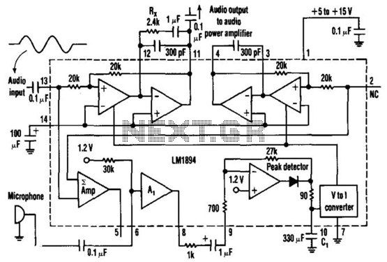
This single-chip circuit adjusts its audio gain according to the ambient noise picked up by the microphone. When operating in a quiet environment, the audio output is quiet, while a noisy environment results in a louder audio output. Audio...
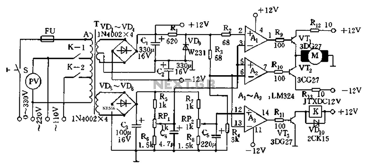
Automatic AC voltage regulator circuit TXD1742 with continuous adjustment. The TXD1742 is an automatic AC voltage regulator circuit designed to provide continuous voltage adjustment, ensuring stable output voltage in varying load conditions. This circuit is particularly useful in applications where...
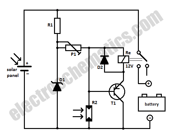
When charging a battery during the day using a solar panel, there is a risk of the battery partially discharging through the panel after sunset. This solar panel power switch circuit eliminates the need for a diode by utilizing...
INTRODUCTION It is essential to monitor the operation of nearly all automated and semi-automated devices, such as washing machines and autonomous systems. Monitoring the functionality of automated and semi-automated devices is crucial for ensuring optimal performance and reliability. This can...
This DC Motor Controller circuit will control a 12V dc motor. The system will have three pushbuttons: a START button, a REVERSE button and a STOP button. Initially, the motor must not be running. When the START button is...
The Controller Area Network (CAN) data rate ranges from 10 kbit/s to 1 Mbit/s, with recommended distances of 40 to 1000 meters using two twisted pairs—one for data and the other for power and ground. Up to 110 nodes...
Warning: include(partials/cookie-banner.php): Failed to open stream: Permission denied in /var/www/html/nextgr/view-circuit.php on line 713
Warning: include(): Failed opening 'partials/cookie-banner.php' for inclusion (include_path='.:/usr/share/php') in /var/www/html/nextgr/view-circuit.php on line 713