
2Hz unsteady pulse single circuit diagram

The described capacitive circuit operates with a low duty cycle, which is advantageous for applications requiring minimal power consumption. The duty cycle, defined as the ratio of the time the circuit is active to the total time period, is set between 1% and 10%. This low duty cycle allows the circuit to conserve battery life, making it suitable for long-term monitoring applications, such as studying animal physiology.
The circuit features a current draw of 50 mA during operation, with a peak battery current consumption of 1 A. This discrepancy indicates that the circuit is designed to operate intermittently, allowing for efficient energy use. The use of resistors and capacitors in the circuit design is critical for timing control. Resistor R4 in conjunction with capacitor C determines the duration of the 'on' time, effectively controlling how long the circuit remains active during each pulse. Conversely, resistor R1 and capacitor C are responsible for the 'off' time, dictating how long the circuit remains inactive before the next pulse.
The pulsing frequency of the circuit is set to twice per second, or 0.5 Hz. This frequency is particularly useful for physiological measurements, such as monitoring animal temperature and heart rate. The choice of this frequency allows for sufficient data collection intervals while minimizing the impact on the subject being monitored.
The overall design of this capacitive circuit emphasizes low power consumption and effective timing control, making it a practical solution for continuous monitoring in biological studies. The integration of resistors and capacitors provides a simple yet effective means to manage the circuit's operational states, ensuring reliable performance in its intended applications. Capacitive circuit duty cycle is very low, in the range of 1-10%. When the current is only 50mA, the battery current consumption is only 1 A. R4 and C control the opening time, and R1 and C control turn-off time. Circuit pulse twice per second, can be used to study animal temperature and heart rate.
Related Circuits
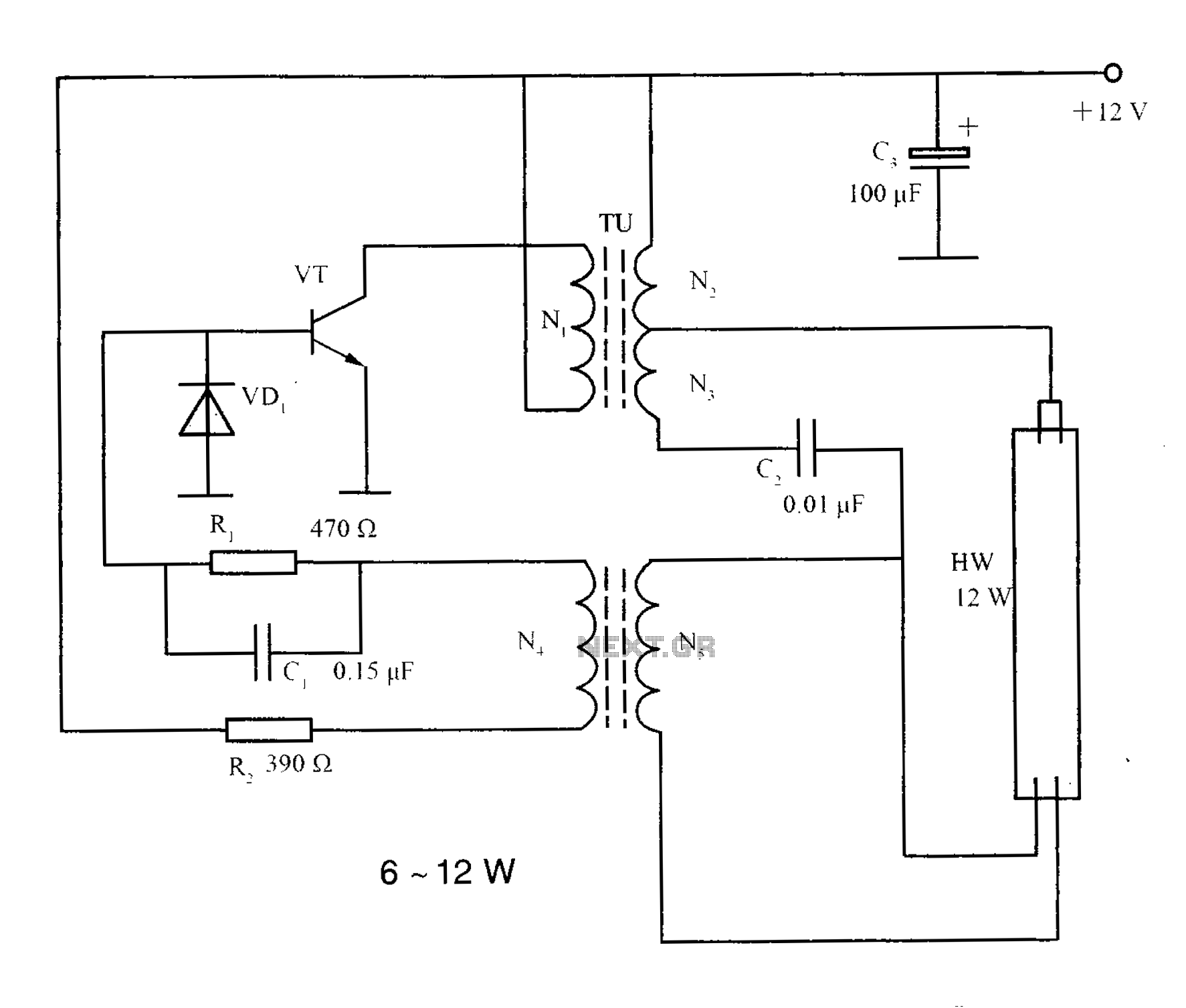
The lighting inverter circuit is designed for 6 to 12W fluorescent lamps. It operates by first bucking the mains voltage, followed by rectification and filtering to charge a battery. When the inverter is activated, it generates a high-frequency alternating...
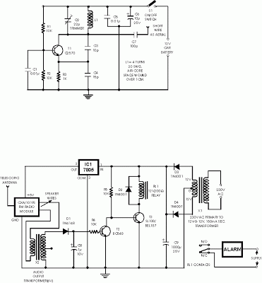
This is an anti-theft alarm with wireless connectivity, referred to as the Anti-Theft Car Wireless Alarm. The FM radio-controlled anti-theft alarm can be utilized with any vehicle that operates on a 6 to 12-volt DC supply system. The mini...
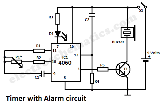
This simple alarm timer circuit is constructed using a 4060 integrated circuit, which features a stable oscillator with a relatively wide frequency range. The alarm timer circuit utilizes the CD4060 IC, which combines a low-frequency oscillator and a binary counter....
The circuit is a battery charging system powered by Q2, Q6, R8, and D10, which provides constant current to charge the battery. When an external power supply is present, the charging current flows through R8 and D10 to charge...
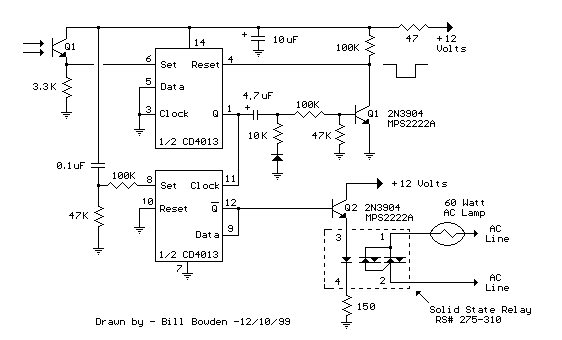
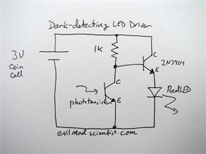
The IR photo transistor Q1 (Radio Shack 276-145A) or a similar component is connected to the set input (pin 6). It is essential to shield the photo transistor from direct light to ensure that the voltage at the set...
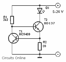
An LED is usually a series resistor needed to ensure that the LED does not get too much power. The disadvantage of such resistance is that the current through the LED and thus the brightness changes as the voltage...