
VU meter circuit for LM3915 PCB
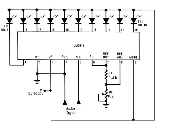
The circuit design based on the LM3915 is particularly effective for applications requiring a visual representation of audio levels, such as in audio mixing or monitoring equipment. The integration of an adjustable voltage reference allows for customization of the threshold levels at which each LED is activated, making it suitable for various input signal ranges. The high-impedance input buffer ensures that the circuit does not load the input signal, preserving the integrity of the audio signal being monitored.
The ten-step voltage divider provides precise voltage levels for the comparators, enabling accurate tracking of the input signal's amplitude. Each comparator corresponds to a specific voltage range, illuminating the respective LED based on the input signal's level. The logarithmic scaling of the display is beneficial for audio applications since human hearing perceives sound levels logarithmically.
Moreover, the ability to handle input voltages up to 35V without additional protection simplifies the design process, allowing for easier integration into existing systems. The programmability of the LED current drive enhances flexibility, enabling the user to adjust the brightness of the LEDs according to their requirements. Overall, this circuit offers a compact and efficient solution for visual audio level monitoring, combining simplicity with high performance.This circuit uses just one IC and a very few number of external components. It displays the audio level in terms of 10 LEDs. The input voltage can vary from 12V to 20V, but suggested voltage is 12V. The LM3915 is a monolithic integrated circuit that senses analog voltage levels and drives ten LEDs providing a logarithmic 3 dB/step analog display L ED current drive is regulated and programmable, eliminating the need for current limiting resistors. The IC contains an adjustable voltage reference and an accurate ten-step voltage divider. The high-impedance input buffer accepts signals down to ground and up to within 1. 5V of the positive supply. Further, it needs no protection against inputs of 35V. The input buffer drives 10 individual comparators referenced to the precision divider. Accuracy is typically better than 1 dB. 🔗 External reference
Related Circuits
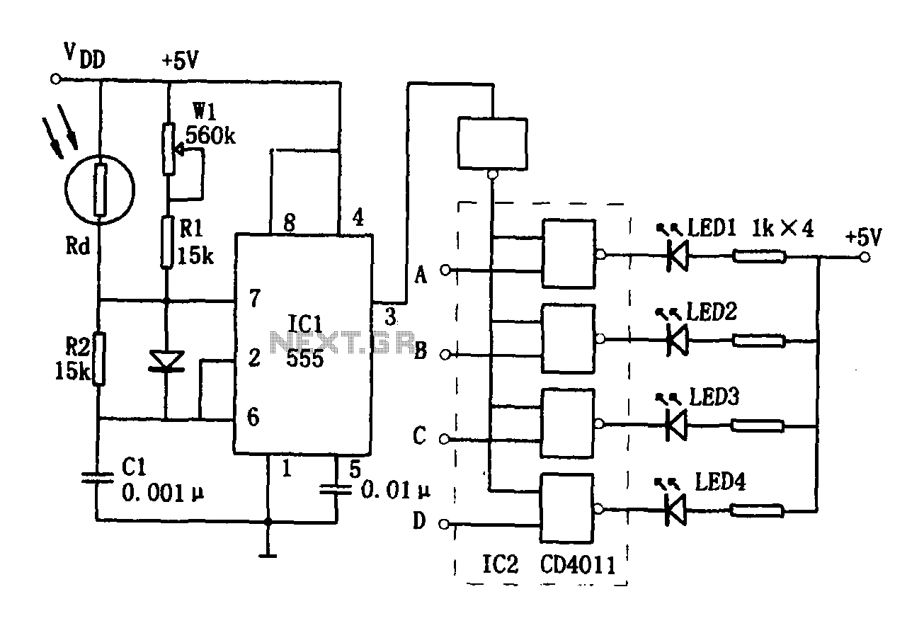
The brightness display circuit consists of a light-sensitive sensor, an oscillation circuit, and an LED display circuit. The light-sensitive sensor is a photosensitive resistor (Rd). The multivibrator is composed of Rd, R1, W1, R2, and C1, along with a...

The circuit diagram illustrates a simple stepper motor controller utilizing basic components. The driver circuit employs four SL100 transistors to control the motor windings, along with two NOT gates and one XOR gate to decode the two-bit control logic...
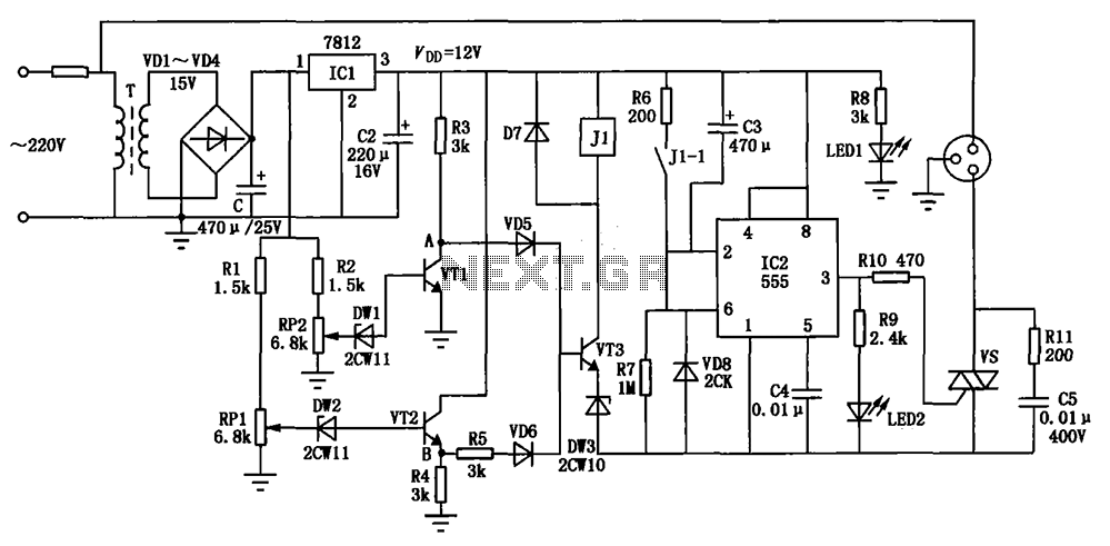
The circuit consists of a DC voltage regulator, a delay circuit, and protection mechanisms for overvoltage and undervoltage. It utilizes the LM7812 integrated voltage regulator to provide a stable 12V output. The protection circuit samples voltage using R2 and...
This supply generates an initial high voltage for ignition purposes. After ignition, the supply generates about 1300 to 1500 V. If a higher ignition voltage (than the 6000 V supplied) is necessary, more multiplier stages can be added to...
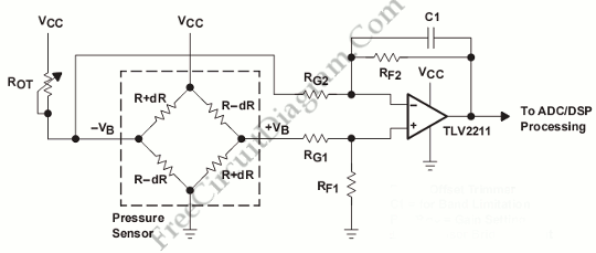
This is a pressure sensor signal conditioning circuit. It is a simple and inexpensive circuit due to its small geometry and the use of a straightforward pressure sensor. The pressure sensor signal conditioning circuit is designed to convert the raw...

The input capacitor is used for low-frequency cut-off, with a standard value of 0.1 µF, resulting in a cut-off frequency of approximately 16 Hz. The input capacitor plays a critical role in electronic circuits, particularly in signal processing and audio...