
3 Digit Display Scoreboard
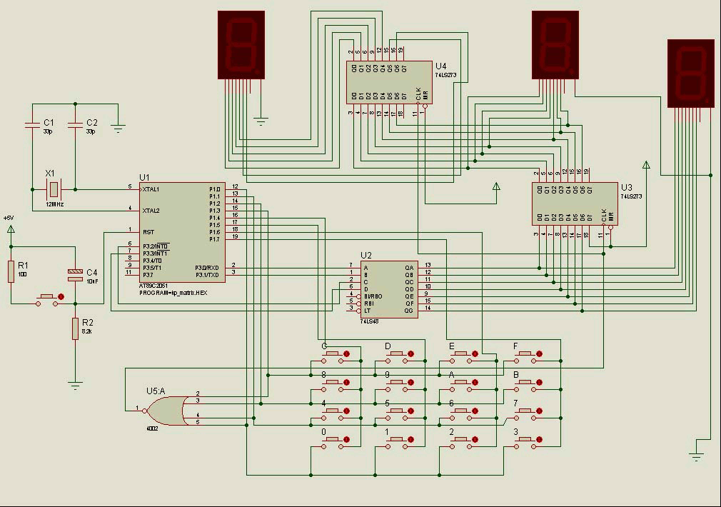
The 3-Digit Display Scoreboard with a 4x4 Keypad Matrix is an electronic circuit that utilizes the 8051 Microcontroller to manage inputs and outputs effectively. The primary function of this circuit is to display scores or numerical values on a 7-segment display, allowing users to keep track of scores in games or other applications requiring numerical input and display.
The circuit comprises several key components: the 8051 Microcontroller, a 4x4 matrix keypad, and three 7-segment displays. The 4x4 matrix keypad serves as the user interface, allowing users to input scores or navigate through options. Each key press is detected by the microcontroller, which processes the input accordingly.
The 7-segment displays are connected to the microcontroller's output pins. The microcontroller is programmed to convert the numerical values from the keypad into a format suitable for display on the 7-segment units. This involves driving the segments of each display to represent the corresponding digits accurately.
Power supply considerations for the circuit include ensuring that the microcontroller and the displays receive appropriate voltage levels, typically 5V. Bypass capacitors may be included to filter any noise from the power supply, ensuring stable operation.
For the design, attention must be paid to the connections between the microcontroller, keypad, and displays. Proper debouncing techniques should be implemented in the software to avoid erroneous readings from the keypad. Additionally, the microcontroller's firmware should be optimized for efficiency, allowing for quick response times to user inputs.
Overall, the 3-Digit Display Scoreboard with a 4x4 Keypad Matrix represents a practical application of the 8051 Microcontroller, demonstrating its capabilities in handling user input and controlling output displays in a user-friendly manner.A few months ago Milardo starting to study the 8051 Microcontroller. From his research Miardo has designed a new circuit and called it 3-Digit Display Scoreboard with 4x4 Keypad Matrix.. 🔗 External reference
Related Circuits

The circuit mentioned is significantly less effective than Lev's Oscillator for Theremin applications. The simulation waveforms indicate the red sine wave represents the voltage on L1:A, the black sine wave indicates the voltage on Q1:D, and the blue square...
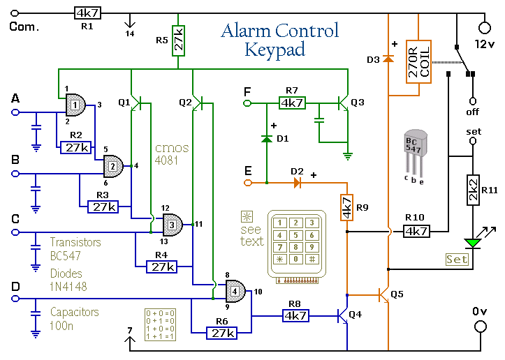
The Keypad must be the kind with a common terminal and a separate connection for each key. On a 12-key pad, look for 13 terminals. The matrix type with 7 terminals will NOT do. The Alarm is set by...
This page presents a replacement circuit for the LM3909 LED Flasher/Oscillator utilizing discrete components. The circuit functions similarly to the integrated LM3909 but features minor variations in the component values used. Although the LM3909 is still available, it tends...

This article introduces a simple solution for beginners and intermediate readers to build a digital-to-analog converter (DAC) using an R/2R resistor network. It also addresses common challenges faced by beginners while constructing their own DACs and offers straightforward solutions....
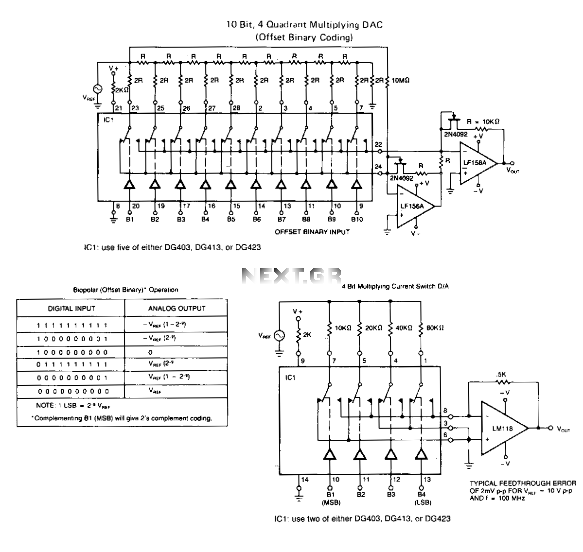
The following application circuits are intended to illustrate specific points: A 2 kΩ resistor should be placed in series with V+ to limit supply current and mitigate negative ringing of the bit inputs. Temperature compensation for Rns(on) can be...
The simplest Analog to Digital Converter (ADC) can be constructed as shown in Figure 1. The input voltage, which can range from zero up to the power supply voltage (Vcc), is converted to a parallel binary code at the...