
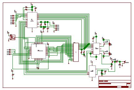
4 order filter with a single IC project PCB
The described fourth-order filter circuit is structured to provide superior performance in applications requiring minimal phase distortion and a smooth frequency response. The use of a single operational amplifier (TL081) not only simplifies the design but also minimizes potential sources of distortion typically associated with multiple stages. The TL081 is a high-performance JFET-input operational amplifier, known for its low noise characteristics and wide bandwidth, making it suitable for audio and precision filtering applications.
The resistor network formed by R1 to R4 establishes a load impedance of 2.5k ohms at the output of the operational amplifier. This impedance is crucial as it defines how the circuit interacts with subsequent stages or loads, ensuring that the maximum load does not exceed the specified 2k ohms limit of the TL081. It is essential to maintain an external load of at least 10k ohms to prevent excessive loading on the operational amplifier, which could lead to performance degradation.
The filter's design employs a Bessel polynomial characteristic, which is particularly advantageous for applications requiring a maximally flat group delay. This characteristic ensures that the phase response of the filter is linear over the passband, making it ideal for audio and signal processing applications where time-domain fidelity is critical.
At the specified component values, the filter exhibits a -3dB cutoff frequency of 1kHz, indicating that signals at this frequency will be attenuated to half of their power level. By adjusting the values of the resistors and capacitors within the circuit, various cutoff frequencies can be achieved, allowing for customization based on specific application requirements.
In conclusion, this fourth-order Bessel filter circuit is an effective solution for applications needing precise frequency response and low distortion, with the added flexibility of tuning to various frequencies through component value adjustments.Circuit Filters with high orders are designed usually with 2 or more cascaded sections. This order 4 filter need only one OA IC, so we can achieve lower distorsions, lower intermodulation Resistors values represent the load on the OA output, the maximum TL081 load is 2k ©. R1-R4 build a 2. 5k © impedance and so the external load cannot be low er than 10k ©. The filter characteristic is a Bessel polinome. With the actual components value, at -3dB the frequency is 1kHz. You can obtain different frequencies by changing the components value. 🔗 External reference
Related Circuits
This circuit is an RMS-calibrated AC voltmeter that provides average readings. Removing capacitor C2 eliminates the averaging function, resulting in a precision full-wave rectifier, while removing capacitor C1 transforms the circuit into an absolute value generator. The operation of...
Any LED can be used for D1 - D10; however, blue LEDs require a higher voltage, which may result in them appearing dimmer compared to red, yellow, or green LEDs. If pin 9 of U2 is left disconnected, the...
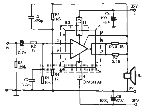
The Burr-Brown OPA541 chip is a power amplifier capable of operating with a maximum power supply voltage of 40V, delivering a continuous output current of up to 5A. The output current can be adjusted using an external resistor to...
In the view of the dramatic drop in the price of crystals used in color TV sets, they now represent an economical way of building an SSB filter. The circuit shown in the diagram is for a filter with...
The vehicle is a 2005 Pontiac GTO equipped with a 6.0L engine and a 6-speed manual transmission. The factory headlights, which utilize H11 low-beam projectors, have been found to provide inadequate illumination, prompting a retrofit. The plan includes mounting...
This is the original Circuit Cellar ImageWise Transmitter that was initially used. The code was disassembled to capture two half-size images, allowing for the extraction of images from both the odd and even fields. Code was then written to...