
4 transistor 500mw fm transmitter

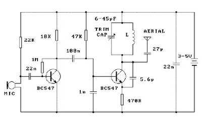
The described audio circuit functions as a basic FM transmitter, leveraging the characteristics of the Colpitts oscillator to generate a stable frequency signal. The use of two 2N3904 transistors as a preamplifier allows for effective amplification of the audio input from the microphone, facilitating clear audio transmission. The adjustable gain provided by the 5k potentiometer enables fine-tuning of the audio levels, ensuring optimal performance based on the input source.
The Colpitts oscillator configuration is notable for its simplicity and effectiveness in generating a stable frequency. The selection of two 5pF capacitors and a 10µH inductor as frequency-determining elements establishes the oscillator's operating frequency. The possibility of substituting these components with variable capacitors offers an opportunity for experimentation and customization, allowing users to modify the operating frequency as needed.
The output stage of the circuit, an RF amplifier, significantly increases the power of the signal generated by the oscillator. With an output of approximately 500mW, the circuit is capable of transmitting signals over a considerable distance, making it suitable for various applications, including amateur radio and short-range communication.
However, it is crucial to consider the implications of operating without an output filter. The absence of filtering can lead to unintended frequency drift and the generation of harmonics, which may interfere with other communication channels. Therefore, users should be aware of regulatory requirements regarding spurious emissions and take appropriate measures to mitigate any potential interference caused by the transmitter's operation. Overall, this circuit serves as an educational platform for understanding basic FM transmission principles, oscillator design, and audio amplification techniques.As shown, the audio ascribe is a microphone, which uses 2 x 2N3904 as the microphone audio preamplifier. The audio/mic ascribe akin is adjustable by agency of a 5k preset / potentiometer. The ambit uses a Colpitts oscillator for abundance generation, which is chargeless active and operates at the axiological abundance i.
e. no circuitous abundance multiplication or control. The abundance affability basic of the ambit consists of 2 5pF (picoFarad) capacitors and a distinct 10uH (micro-Henry) inductor. These apparatus can be adapted if a change in abundance is appropriate - conceivably alike replaced with capricious capacitors (if you`re up to the challenge).
An achievement RF amplifier takes the abundance produced by the Colpitts oscillator and amplifier to about about the 500mW (0. 5 Watt) ambit - so this is the almost achievement ability of this FM transmitter. You are brash that back this transmitter operates at the axiological frequency, and because there is no achievement filter, there is acceptable to be some abundance alluvion and harmonics/spurious emissions.
🔗 External reference
Related Circuits

This circuit is a simple metronome model designed for ease of use. It employs transistors as key components, specifically configured as an astable multivibrator, to produce a beeping sound. The tone can be adjusted using a variable resistor (VR1)....
The AVR Basic Infrared Transmitter is a companion project to the Basic Infrared Receiver. This project is termed "basic" because it can be constructed using only 10 discrete components along with a standard AVR microcontroller. Together, these two projects...

This is the simplest single transistor FM wireless transmitter circuit ever posted in CircuitsGallery. In the field of telecommunications, frequency modulation (FM) transmits information by altering the frequency of a carrier wave based on the message signal. FM utilizes...
This circuit consists of five transistor time relay circuits designed for time relay exchange. It utilizes two different power supplies, maintaining the same circuit configuration. The delay time can be adjusted by modifying a potentiometer. The parameters for the...
An FM modulator that modulates a carrier frequency with the composite signal, and an RF amplifier that provides enough power to be transmitted through an antenna. Here is the schematic diagram of the FM transmitter circuit: The core of...
Place the transmitter approximately 10 feet away from an FM radio. Set the radio to a frequency between 89 and 90 MHz. Walk back to the FM transmitter and turn it on. Separate the windings of the coil by...
Warning: include(partials/cookie-banner.php): Failed to open stream: Permission denied in /var/www/html/nextgr/view-circuit.php on line 713
Warning: include(): Failed opening 'partials/cookie-banner.php' for inclusion (include_path='.:/usr/share/php') in /var/www/html/nextgr/view-circuit.php on line 713