
Diode tester
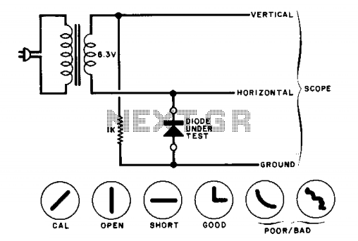
The described circuit is designed to visualize the behavior of a diode through an oscilloscope. The diode's state, whether forward-biased or reverse-biased, will influence the waveform displayed on the oscilloscope. In forward bias, the diode conducts, allowing current to flow and producing a characteristic voltage drop, while in reverse bias, it blocks current flow, resulting in a different voltage characteristic.
For calibration purposes, the diode can be temporarily replaced with a 1000-ohm resistor. This substitution allows for a controlled measurement of the voltage across the resistor, which can be used to set the oscilloscope gains accurately. The objective of adjusting the oscilloscope settings to display a 45-degree line indicates that the circuit is likely intended to demonstrate a linear relationship between voltage and current under certain conditions.
The expected results, as indicated in the drawings, may include various waveforms corresponding to different states of the diode. These could range from simple linear responses to more complex nonlinear behaviors, highlighting the diode's characteristics such as forward voltage drop and reverse recovery time. The oscilloscope serves as a critical tool in visualizing these electrical phenomena, providing insight into the diode's operational limits and performance in various circuit configurations.The circuit will display curves on a scope, contingent on the state of the diode. To ' 'calibrate,'' substitute a 1000-ohm resistor for the diode and adjust the scope gains for a 45-degree line. The drawings show some expected results. 🔗 External reference
Related Circuits
This design will interest technicians who work on pneumatically operated valves and other 4-20mA current loop controlled devices. Although the 4-20mA signal is commonly used in industrial applications for transmitting sensor data and controlling devices, it is essential to...
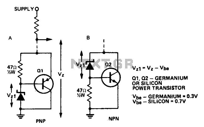
A power transistor can be utilized to supply a high-powered Zener voltage from a low-wattage Zener diode. A 400 mW Zener diode can be employed in applications requiring a 10-watt Zener, or a 1 W Zener can be used...
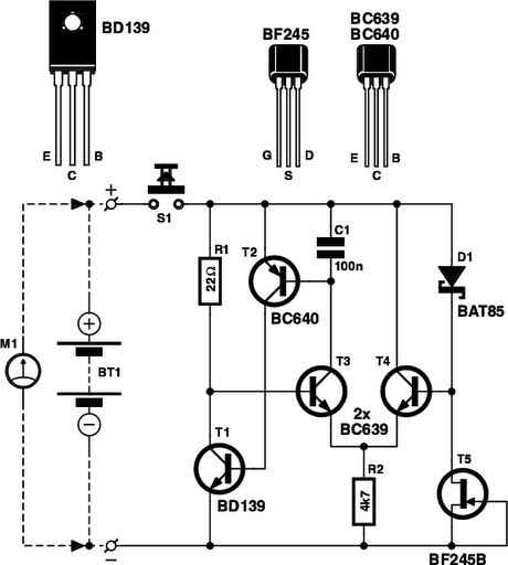
Is the battery depleted, or is there an issue with the device? This question often arises when a battery-operated device, such as a Walkman, fails to power on. Before seeking professional repair services, it is advisable to first test...
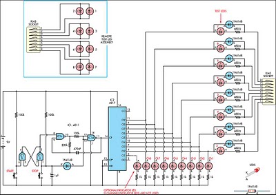
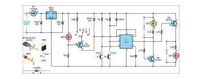
This circuit was developed to create a simple network tester that can be operated by a single individual. Commercial units typically require a second person to monitor the remote LEDs, as the transmitters lack the ability to continuously cycle...
This circuit illustrates a Go-No/Go Tester Circuit utilizing a 555 Timer IC. Features include a more advanced unit with a precise timed testing procedure. The Go-No/Go Tester Circuit is designed to evaluate components or assemblies by providing a simple pass/fail...
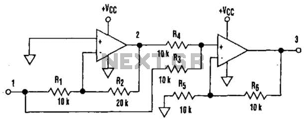
It is well understood that utilizing single-supply operational amplifiers (op amps) can present challenges when implementing simple functions in a bipolar signal environment. Often, this necessitates the use of additional op amps and other electronic components. Considering this, it...
Warning: include(partials/cookie-banner.php): Failed to open stream: Permission denied in /var/www/html/nextgr/view-circuit.php on line 713
Warning: include(): Failed opening 'partials/cookie-banner.php' for inclusion (include_path='.:/usr/share/php') in /var/www/html/nextgr/view-circuit.php on line 713