
de amst wiskar: robot line folower
The robot design incorporates a dual stepper motor system controlled by the L293 driver chip, which is configured to form an H-Bridge, allowing for bidirectional control of the motors. The use of external diodes is critical for preventing back EMF damage, particularly when dealing with inductive loads such as motors. The C-52 Evaluation Board serves as the main controller, interfacing with the L293 driver through dedicated pins for PWM control and motor direction. The implementation of PWM allows for speed modulation, which is essential for fine-tuning the robot's performance during its operation on the black tape.
The design process encourages creativity among competitors, as they are tasked with developing their own line tracking sensors. The flexibility in sensor design promotes experimentation with various components, such as comparators and LDRs, which may necessitate additional ADC capabilities. The integration of the PIC16C711 ADC provides a cost-effective solution for enhancing the sensor's functionality, enabling the microcontroller to process analog inputs effectively.
A well-structured power supply circuit is essential for ensuring reliable operation of the robot. The LM317 voltage regulator is utilized to provide a stable voltage supply, with careful consideration given to the charging circuit for rechargeable batteries. The PWM control method employed for motor operation not only optimizes power usage but also enhances the responsiveness of the robot, allowing it to navigate the competition track efficiently.
Overall, the project fosters a practical understanding of robotics, programming, and circuit design, while providing a platform for students to showcase their skills in a competitive environment. The collaboration and sharing of ideas among participants will likely lead to innovative solutions and improvements in their robotic designs.One of my student has made a disgraceful robot that used two stepper motors and with a simple IR sensor. Yes, above picture is what I`m talking. Without battery carrying, a little bit torque of the stepper and misalignment of driving shaft, makes it crawling not walking, but first demo, showed quite impressive to me.
He said he wrote a couple of p rogram lines using C, his robot can track the black tape. I feel delighted his intention and endeavor. I thought, " he borrowed me DS5000, expensive one, a soft uController with internal bootloader, why shouldn`t try with our learning board C-52 Evaluation Board instead". Another one, told me the same day "I found the L293 Push/Pull Four Channel Driver at Ban-Moah, it costs 1.
5 US$ ". I`ve been searching this chip for a year. The MiniBoard, a Motorola 68HC11 Robot Controller board designed by Fred G. Martin, also uses this driver. The day after, I then decided to prepare the page describing how to use C-52 EVB as a robot controller board. I asked my student for competition, build yourselves robot that can track the black tape. Prize for the winner is 100 US$, with a bit condition that the winner must pay for a big party at Soi Jinda`s Somtum (Papaya Salad) shop.
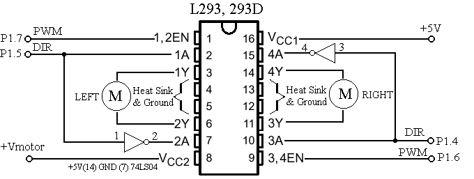
And one of the competitor is me. I thought the rule should be conceived roughly by students and technically by me. The picture on that day will put here soon. Basic circuit of using L293 forms an H-Bridge Driver is shown in Figure 1. As shown for such inductive load as DC motor, external diodes for suppressing back EMF must be connected. The MiniBoard uses L293D instead, the L293D has internal diodes, however providing a bit less driving capacity, i.
e. , 600mA @4. 5V-36V. From the truth table, we see that direction of the motor can control by pin C and D. VINH enable/disable power to the motor, thus for speed regulation, we then use this pin for PWM signaling. See details, L293. pdf data sheet. A circuit connecting C-52 P1 to L293 driver chip is shown in Figure 2. As shown Enable pin 1 connected to P1. 0 is for PWM signaling. We use additional inverter at pin7 and pin 15 to provide proper logic for easy directional control. Please note that pin 4, 5, 12, 13 are tied to ground and if heat sinking needed, one method is to make a large area of PCB or soldering it with a metal sheet, say.
Figure 2: Connecting C-52 EVB P1. 4-P1. 7 to L293. External diodes must be connected for L293(not shown in circuit diagram). My latest design put additional inverter for PWM signal at pin 1 and pin 9 to prevent full power delivering to DC motors when resetting the 89C52(i. e. , all bits of P1 is logic high). Check the logic of PWM pins for another microcontrollers. Since there`s no ADC for 89C52 chip, each competitor may build their own Line Tracking Sensor, some may use LM339 QUAD comparator with IR transmitter and receiver, some may use LDR as described in Line Follower Robot.
With an external comparator, it may not necessary to have ADC, but with LDR, we need external ADC. " Having additional ADC for 89C52 would be better", I thought. How can we provide ADC for 89C52 with a cheap method I chose PIC16C711 with 4-channel ADC, and 7-pin input port. Interfacing to 89C52 is done with simple PISO protocol by using RB0 for SCLK and RA4 for SDA. The code for such purpose was written in C, here is the source file, C52ADC. C and the HEX code, C52ADC. HEX. After some initialization, the 711 chip wait for trigger read signal at pin RB0, i. e. , high-to-low transition, then it responses by sending 40-bit through RA4(SDA) with low-to-high transition.
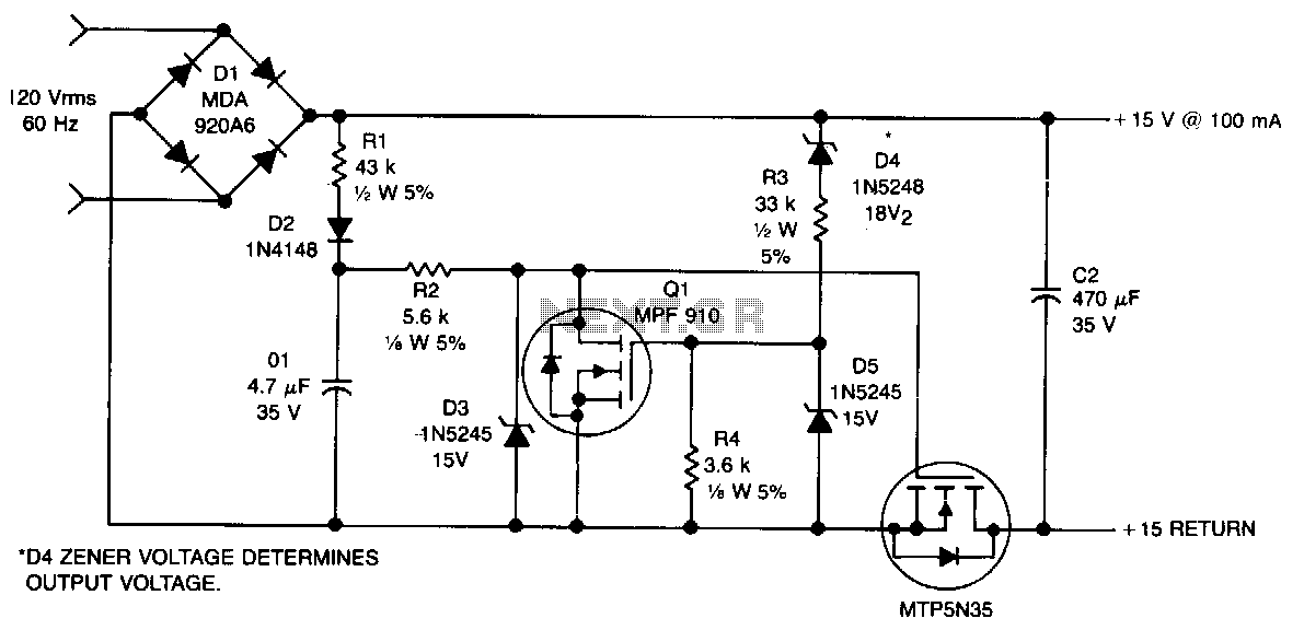
40-bit data stream begins with LSB of ADC0 to MSB of PORT B. Example of program fro testing ADC is ADC. C and the hex file is ADC. HEX. Figure 4 shows a simple power supply circuit. I have tested with KABO, it works fine. For those who have a big capacity rechargeable battery, the resistance value of R can be selected for approx. 10% output charging current. DC in can be higher if your battery voltage higher than 8. 4V, say. To ensure the output current is within the value calculated by R, measure DC current before. The maximum supply for LM317 is ~35V. Figure 4: Circuit Diagram of battery supply +12V Alkaline and +8. 4V NiMH with a constant current recharger circuit. For ~20mA, use R~60 Ohms. S1 is main switch for CPU and L293 circuits. Before writing PWM generation for testing above circuit, let study how to use Paul`s header. With a PAUL`s startup header at the beginning of the application C program, after successfully downloading the hex code, just press RESET, the 89C52 then will run the application instead of PAULMON2 monitor program.
As long as the program remain in SRAM, running the program can only be done with pressing RESET. To return to PAULMON2 prompt, turn the board power off for a while, then back the power on again. This concept of startup header allows us to use C-52 EVB as a dedicated controller beside as a learning board. Originally Paul has made with entirely in Assembly code. However, I have adapted for Micro-C Compiler. I have put the header for startup code in the startup and runtime library for small memory model. The file C52ROBOT. ASM, will compile and link to the main( ) function with S=c52robot. asm when invoking command coordinator. Example of command line is; One method of delivering DC power to motors is to use PWM. The PWM method supplys DC pulse with fixed frequency but with adjustable duty cycle. I used TIMER2 in AUTO reload producing 1000Hz PWM frequency. Each time executing has entering into service routine, a 16-bit PWM1 was shifted out to P1. 7 and PWM2 to P1. 6. Main program has a task that set the power for motor1 and motor2 by writing 16-bit PWM pattern into PWM1 and PWM2 for motor1 and mortor2 respectively.
The service routine for timer2 is put in startup code. See example program, KABO1. C and C52ROBOT. ASM, for PWM demonstration with manual control. I have designed and built my own robot for the competition also. It names KABO having differential drive method. As shown in right-hand side, is the rare part powered by C52-EVB. The motor driver chip L293D and a 74LS04 are put at the soldering pad. I suppose there should have ten robots to be competed. Details Rule and Scoring will be launched soon, day by day changed. But first of all, competitors must know how difficult of the circuit and programming are. Hear is the actual course layout. The original idea of what kind of the competition would be, came from Zongwit. Each round has two robots. Each robot must run along black tape and try to touch the the other`s target. Who touch first will be the winner. The slower is allowed to detect the faster, shifted out of the line for 20 seconds, then back again. No limit for the robot size and uControllers, you may use ranging from a PIC16F84, 16F873/877, 89C2051/4051, 89C51/52/55, or 68HC11, say. 🔗 External reference
Related Circuits
Introduction to the Reflow Process and PID Controller Circuit Documentation. This document discusses the benefits of using Surface Mount Devices (SMD) in circuit design, highlighting advantages such as reduced size and cost compared to traditional through-hole components. The reflow soldering...
The principles of DC motors are discussed in the beginner and intermediate sections of this tutorial. This section will address the electronics required to interface them with a Basic X microcontroller or other digital chips. The simplest method of...
The circuit described can connect two telephones in parallel and function as a two-line intercom. Typically, a single telephone is connected to a telephone line. When another telephone is needed at a distance, a parallel line is utilized for...
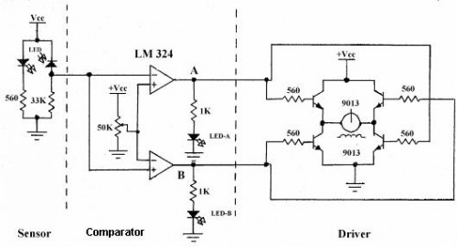
Line follower robots are commonly designed to follow a specific path on a track. Typically, these robots are controlled by microcontrollers; however, this article discusses a line follower robot designed without using a microcontroller. The assembly consists of three...
This non-isolated, unregulated converter with minimal components serves as a bridge between low-power zener regulation and the higher power applications of a 60-Hz input transformer. It is designed for scenarios where a non-isolated power supply can be utilized safely....
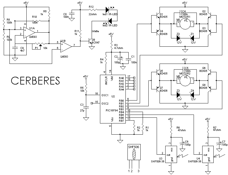
When the 36 kHz infrared light emitted by the LEDs is reflected off an object, one of the receiver modules is activated. The PIC16F84 microcontroller then directs the robot to avoid the object by reversing one of the motors. The...