
4W FM Transmitter

The 4W FM transmitter is designed to operate within a frequency range of 88 to 108 MHz, which is the standard FM broadcast band. This device requires a stabilized power supply voltage ranging from 12 to 16 volts, ensuring consistent performance across various operating conditions. The transmitter's current consumption varies between 100 to 400 mA, depending on the output power and operational mode.
The circuit typically includes a modulation stage, an oscillator, and a power amplifier. The oscillator generates the carrier frequency, which is modulated by the audio signal input. The modulation can be achieved using various techniques such as frequency modulation (FM) or phase modulation (PM), with FM being the most common for broadcasting applications.
The power amplifier stage boosts the modulated signal to a level suitable for transmission. Careful attention must be paid to the design of this stage to minimize distortion and ensure high linearity, which is crucial for maintaining audio quality. The output stage may also include a low-pass filter to suppress unwanted harmonic frequencies, ensuring compliance with regulatory standards for emissions.
In addition, the transmitter may incorporate features such as an audio preamplifier, which enhances the audio input signal before modulation, and a feedback loop for automatic gain control (AGC) to maintain consistent output levels despite variations in input signal strength.
Additional components may include capacitors for coupling and bypassing, inductors for tuning, and resistors for biasing and load matching. The overall layout of the circuit should adhere to best practices in RF design, including proper grounding, shielding, and component placement to minimize interference and optimize performance.
This FM transmitter can be utilized in various applications, including community radio stations, educational projects, and personal broadcasting, making it a versatile component in the field of electronic communications.4W FM Transmitter. TECHNICAL CHARACTERISTICS: Stabilised tendency of catering: Vcc=12~16V Frequency of emission: 88~108MHz Consumption: 100~400mA Materially: The. 🔗 External reference
Related Circuits
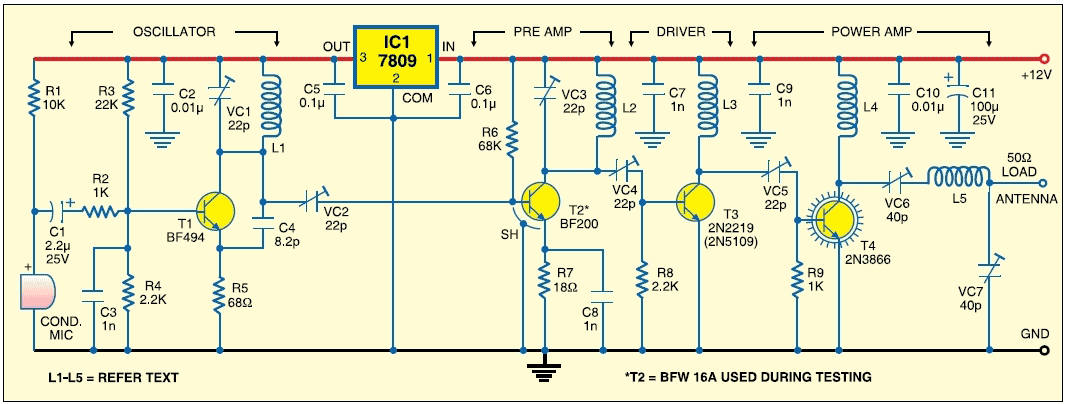
This FM transmitter circuit employs four radio frequency stages: a VHF oscillator built around the transistor BF494 (T1), a preamplifier constructed with the transistor BF200 (T2), a driver using the transistor 2N2219 (T3), and a power amplifier based on...
The transmitter circuit described here includes an additional RF power amplifier stage following the oscillator stage, which increases the power output to 200-250 milliwatts. When used with a properly matched 50-ohm ground plane antenna or a multi-element Yagi antenna,...
This FM transmitter circuit is very simple and has acceptable transmission. The signal transmitted from this FM transmitter circuit can be received at almost 300 meters in open air. The circuit requires a 3-volt operating voltage and can be...
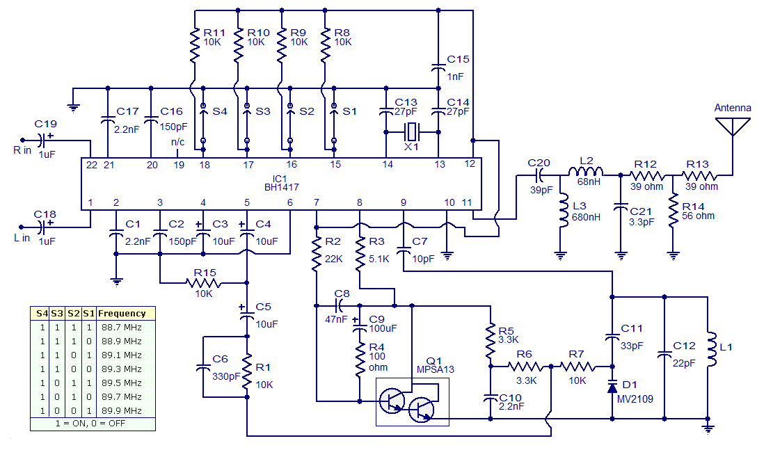
The circuit presented is a simple stereo FM transmitter capable of transmitting high-quality signals over a range of 70 feet. It utilizes the BH1417 PLL Stereo Transmitter IC from Rhom, which features distinct sections for audio processing of the...
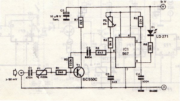
The transmitter is equipped with an LM567 tone decoder circuit. An audio signal (at least 50 mV peak-to-peak) is amplified with a transistor (T1) and then used to modulate IC1. The infrared transmitter frequency is adjusted with potentiometer P2...
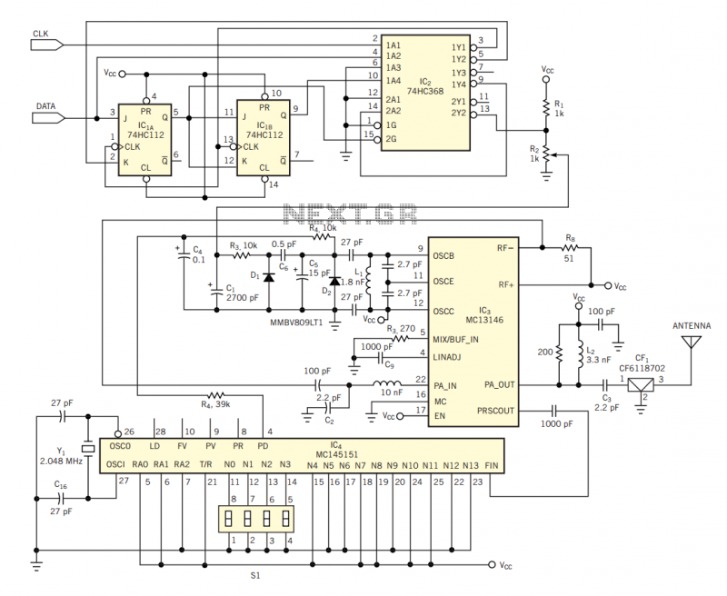
The circuit in Figure 2 shows a 16-channel, AMI-encoded RF transmitter for data rates as high as 28.8 kbps. The circuit operates in the unlicensed (FCC Part 15) 902- to 928-MHz industrial, scientific, and medical (ISM) band and is...