
5.1 Surround Amplifier
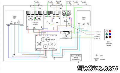
The 5.1 surround sound amplifier circuit is designed to enhance audio output for home theater systems by providing a multi-channel audio experience. The configuration includes six amplifiers: five channels for surround sound (left, center, right, left surround, right surround) and one subwoofer channel, which is responsible for low-frequency effects.
Each channel amplifier is typically based on a specific amplifier IC or discrete components that can handle the required power output. The left, center, and right channels are often designed to operate at higher power levels to ensure clear dialogue and music reproduction, while the surround channels can be optimized for lower power levels since they primarily handle ambient sounds.
The subwoofer channel is critical for delivering deep bass and is usually equipped with a low-pass filter to ensure that only low-frequency signals reach the subwoofer driver. This filter can be implemented using passive components such as capacitors and inductors or active components like operational amplifiers.
In addition to the amplification stages, the circuit design includes various support components such as power supply circuits, volume controls, and tone controls, which may be implemented using potentiometers or digital control interfaces. The circuit may also incorporate protection features to prevent damage from overheating or short circuits, ensuring reliable operation over extended periods.
Overall, the 5.1 surround sound amplifier circuit is a complex integration of multiple audio channels, each with distinct roles, designed to deliver an immersive audio experience for home theater applications.Circuit Making Home Theater 5.1 Surround amplifier schematics Circuit Electronics, Actually, 5.1 channel amplifier consists of 6 amplifiers 1 channel mono, which has certain specifications on each canals. Has 6 channel surround sound ampli.. 🔗 External reference
Related Circuits
The VCA project demonstrates the use of the VCA_Setup and VCA_Data components in ADS. These components belong to the ADS behavioral model suite located under the System - Data Models palette. The schematic "Amp_wBothMatches_setup.dsn" is designed to extract circuit-level...
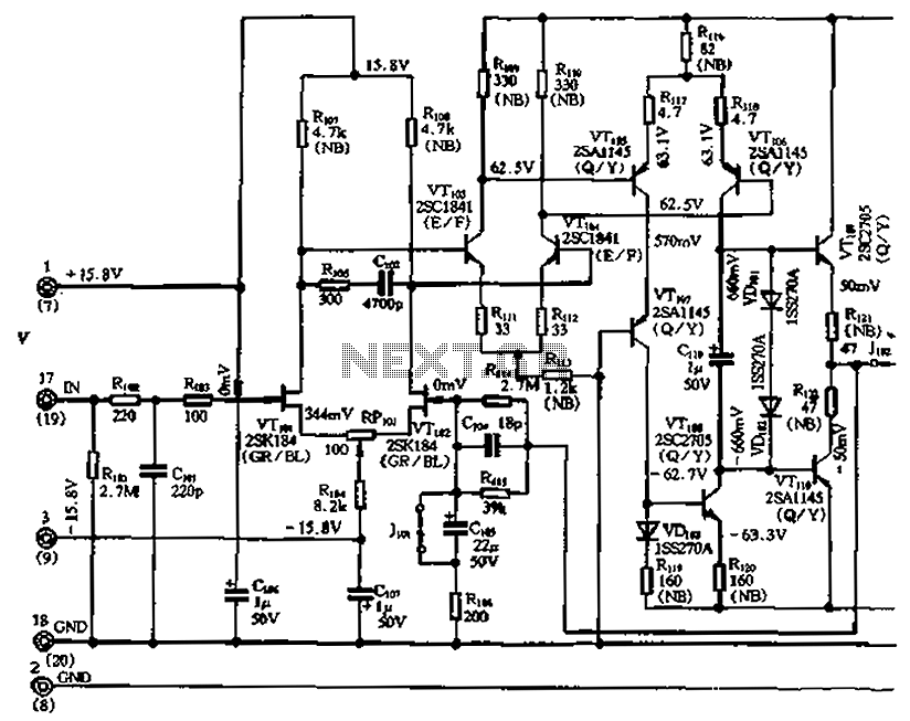
The circuit features a differential input stage that implements differential voltage amplification, forced differential voltage amplification, and a complementary push-pull amplifier output. It includes a bias circuit, a distortion servo circuit, and a protection circuit. The input preamplifier stage...
A few years ago, a decision was made to eventually replace a decades-old Nakamichi stereo system with a more mobile-friendly alternative. It became apparent that Class-D and Class-E switching amplifiers, which had been researched in the 1970s, were experiencing...
Turns off your amplifier when idle for 15 minutes. Fed by amplifier tape-output. This circuit turns off an amplifier or any other device when a low-level audio signal fed to its input is absent for 15 minutes at least....
In addition to its primary function as a headphone amplifier, this circuit is applicable in various scenarios requiring a wide bandwidth low power amplifier. It utilizes an operational amplifier (op-amp) with its output current enhanced by a pair of...
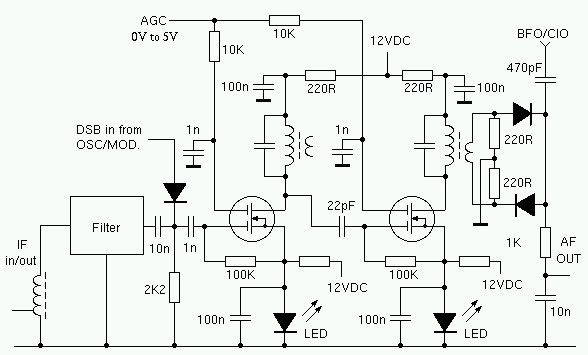
The I.F. amplifier is similar to the one used in the 80M receiver project. The original design has been modified by putting a couple of LEDs in the source circuit of each MOSFET. The voltage drop across the LEDs...
Warning: include(partials/cookie-banner.php): Failed to open stream: Permission denied in /var/www/html/nextgr/view-circuit.php on line 713
Warning: include(): Failed opening 'partials/cookie-banner.php' for inclusion (include_path='.:/usr/share/php') in /var/www/html/nextgr/view-circuit.php on line 713