
555
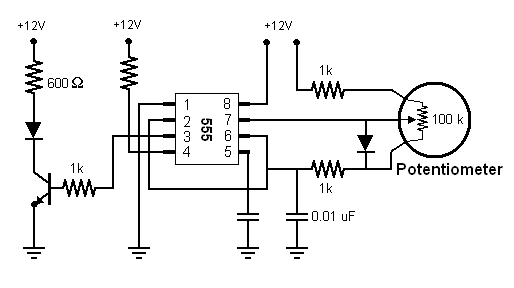
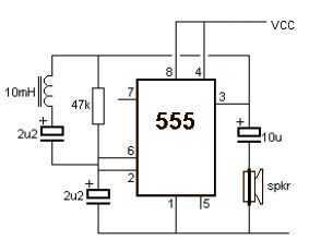
This circuit employs a 555 timer in astable mode to generate a PWM signal that effectively controls the brightness of an LED. The configuration includes a diode, which ensures that one resistor is exclusively responsible for charging the capacitor while the other resistor handles the discharging process. This separation of tasks enhances the precision of the PWM signal and improves the overall performance of the circuit.
The potentiometer connected in series with the resistors allows for fine-tuning of the charging and discharging times, directly affecting the duty cycle of the PWM signal. As the potentiometer is adjusted, the ratio of the time the LED is on versus the time it is off changes, resulting in visible variations in brightness.
The transistor, functioning as a switch, is triggered by the output from the 555 timer. When the timer outputs a high signal, the transistor enters its saturation region, allowing current to flow from the collector to the emitter and powering the LED. The voltage at the junction of the LED and the transistor drops during this phase, indicating that the LED is illuminated. Conversely, when the timer output goes low, the transistor turns off, preventing current flow and causing the voltage at the junction to rise, turning the LED off.
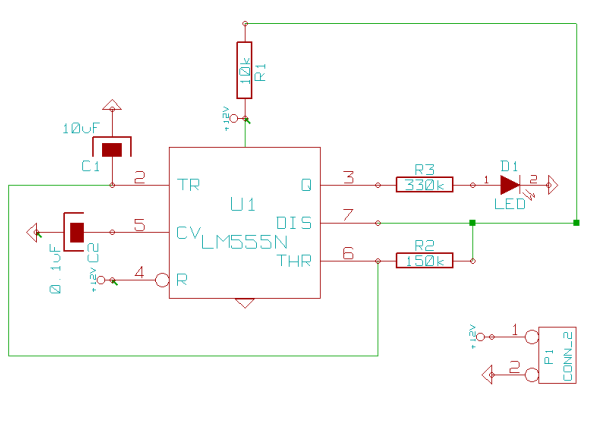
The incorporation of the diode in the circuit allows for longer pulse durations, which can be observed in the simulation results. The simulation demonstrates the charging characteristics of the capacitor and the corresponding voltage across the LED, providing insights into the circuit's operation. The presence of additional pulses in the simulation indicates that the transistor is allowing current to pass through the diode for extended periods, resulting in a brighter LED.
Overall, this PWM circuit utilizing the 555 timer chip effectively demonstrates the principles of pulse modulation in controlling LED brightness, showcasing a practical application of electronics in light control systems.I learned that you could do PWM with the 555 chip. So I tested this idea. I will not attempt to explain the workings of the 555 chip because I found the page by Tony van Roon to be an excellent introduction to the 555 chip. Tony`s page discusses a slightly different setup that what I tested. The key difference is an additional diode. I added this diode so that one resistor is dedicated to the charging the capacitor and the other resistor is dedicated to the discharge process. I added a potentiometer to vary the charging and discharging resistor. Here is my schematic: This circuit uses Pulse Width Modulation to change the LED from dim to bright as the potentiometer is turned.
Here is a simulation that closely resembles my circuit. I modified the capacitor so the simulation would run slower. The graphs show the capacitor and the voltage following the LED. When the 555 chip sends a pulse to the transistor, the transistor will allow current to pass from the collector to the emitter. The LED will light and the voltage at the junction of the LED and transistor will drop. When no pulse is sent, the transistor prevents the flow of current through the LED. In this case, we will see a high voltage at the junction of the LED and transistor. In this photo, we see a few more pulses at the bottom. This indicates the transistor is allowing current to pass through the diode in longer durations. The diode appears a little brighter in this photo. In this case, the 555 chip is sending long pulses to the transistor. The transistor is allowing current to pass most of the time. Thus, the voltage at the junction of the transistor and LED is low (most of the time). This results in the near solid line. 🔗 External reference
Related Circuits
The two circuits below illustrate using the 555 timer to close a relay for a predetermined amount of time by pressing a momentary N/O push button. The circuit on the left can be used for long time periods where...
This is a driving relay circuit utilizing a 555 integrated circuit (IC). The circuit is designed to control a relay and prevent the 555 IC from becoming unresponsive by employing inductive feedback. The coil is safeguarded. The driving relay circuit...
This page outlines how to create a simple theft deterrent that can be quite effective. The concept involves using a flashing red LED to indicate that the vehicle is protected. This device serves to safeguard the car from potential...
This circuit illustrates a Wiper Speed Control Circuit Diagram. The sweeping rate of the wiper can vary from once per second to once every ten seconds. The Wiper Speed Control Circuit is designed to regulate the speed of windshield wipers...
A very simple metal detector electronic project can be designed using a simple 555 timer integrated circuit. As you can see in the schematic circuit, this electronic project requires few external electronic parts. This circuit detects metal and also...
Some simple 555 and flip-flop circuits are being developed to add electronic lighting effects to modernize games. Various circuits are being collected for different game aspects, such as idle states, flipper shots, flower openings, winning shots, etc. A collection...