
multivibrator

The bistable multivibrator is a critical component in digital electronics, serving as a memory element or a basic storage device. The circuit typically consists of two bipolar junction transistors (BJTs), resistors, and capacitors arranged to create feedback loops that stabilize the output states. The feedback mechanism is essential for maintaining the state of the circuit. When a trigger pulse is applied to the base of one of the transistors, it forces the other transistor into its OFF state, thus ensuring that the circuit remains in one of its two stable states until a subsequent trigger pulse is received.
In practical applications, the bistable multivibrator can be utilized in flip-flop configurations, data storage elements, and various timing applications. The design can be modified to suit specific needs by adjusting the resistor and capacitor values, which can influence the switching speed and stability of the circuit. Additionally, variations such as the self-bias and emitter-coupled configurations can provide advantages in terms of power consumption and response time, making the bistable multivibrator a versatile tool in electronic circuit design.
Understanding the behavior of multivibrators, particularly the bistable type, is essential for engineers working with digital logic systems, as they form the backbone of memory storage and state retention in various electronic devices.Multivibrators, like the familiar sinusoidal oscillators, are circuits with regenerative feedback, with the difference that they produce pulsed output. There are three basic types of multivibrator, namely the Bistable Multivibrator, the Monostable Multivibrator and the Astable Multivibrator.
A bistable multivibrator circuit is one in which both LOW and HIGH output states are stable.
Irrespective of the logic status of the output, LOW or HIGH, it stays in that state unless a change is induced by applying an appropriate trigger pulse. As we will see in the subsequent pages, the operation of a bistable multivibrator is identical to that of a flip-flop.
Figure 1 shows the basic bistable multivibrator circuit. This is the fixed-bias type of bistable multivibrator. Other configurations are the self-bias type and the emitter-coupled type. However, the operational principle of all types is the same. The multivibrator circuit of Fig. 1 functions as follows. In the circuit arrangement of Fig. 1 it can be proved that both transistors Q1 and Q2 cannot be simultaneously ON or OFF. If Q1 is ON, the regenerative feedback ensures that Q2 is OFF, and when Q1 is OFF, the feedback drives transistor Q2 to the ON state. In order to vindicate this statement, let us assume that both Q1 and Q2 are conducting simultaneously.
Owing to slight circuit imbalance, which is always there, the collector current in one transistor will always be greater than that in the other. Let us assume that IC2 > IC1. Lesser IC1 means a higher VC1. Since VC1 is coupled to the Q2 base, a rise in VC1 leads to an increase in the Q2 base voltage. Increase in the Q2 base voltage results in an increase in IC2 and an associated reduction in VC2 Reduction in VC2 leads to a reduction in Q1 base voltage and an associated fall in IC1, with the result that VC1 increases further.
Thus, a slight circuit imbalance has initiated a regenerative action that culminates in transistor Q1 going to cut-off and transistor Q2 getting driven to saturation. 🔗 External reference
Related Circuits
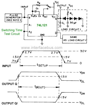
The pinout diagram for the 74L121 and 74L122 integrated circuits (ICs) is applicable to any style of 74xx121 or 74xx122 dual in-line package (DIP) chip, although the timing graphs are only relevant for the indicated TTL families. The 74121...
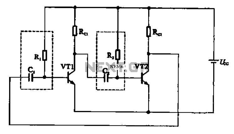
An astable multivibrator is constructed using multiple electronic components and is commonly utilized in pulse signal generation circuits. It operates as depicted in Figure 17-18. The configuration involves two transistors, VT1 and VT2, coupled to capacitor C2 and resistor...
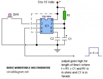
The following circuit illustrates a basic monostable multivibrator, which is based on the 555 Timer IC. Key features include pin 4 functioning as the RESET pin, with the time period defined by the equation t = R1 x C1. The...
Electronics tutorial about multivibrators, including monostable multivibrator circuits, astable multivibrators, bistable oscillators, and clocks. Multivibrators are essential electronic circuits that generate specific output waveforms based on their configuration. They are classified into three primary types: monostable, astable, and bistable multivibrators....
Two 47k ohm resistors, with alternative values ranging from 22k to 100k ohm, can be used. The value of these resistors affects the timing of the blinking; larger values result in slower blinking. In a typical electronic circuit designed for...
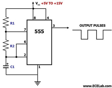
This circuit diagram illustrates the configuration of a 555 timer integrated circuit (IC) as an astable multivibrator. An astable multivibrator is a timing circuit characterized by unstable 'low' and 'high' states. Consequently, the output of an astable multivibrator continuously...