
555 Timer Astable calculator for Astable Multivibrator Designing

The astable multivibrator circuit using a 555 timer IC operates in a continuous oscillation mode, generating square wave signals. This configuration does not have a stable state; it continuously switches between its high and low states, making it ideal for applications such as clock pulses, tone generation, and LED blinking.
In the 555 timer astable configuration, the timing intervals are determined by the external resistors (R1, R2) and the capacitor (C1). The frequency (f) of the oscillation can be calculated using the formula:
\[ f = \frac{1.44}{(R1 + 2R2) \cdot C1} \]
The duty cycle (D) can be derived from:
\[ D = \frac{(R2)}{(R1 + 2R2)} \times 100\% \]
The time periods for the high (Ton) and low (Toff) states are given by:
\[ Ton = (R1 + R2) \cdot C1 \]
\[ Toff = R2 \cdot C1 \]
To meet specific timing requirements, such as Ton = 3 seconds and Toff = 15 minutes, one can manipulate the values of R1, R2, and C1. Given the significant difference between the desired on and off times, it is crucial to select a capacitor with a suitable capacitance value and resistors that can provide the necessary resistance range.
For instance, if a larger capacitance value is required, it may be necessary to use electrolytic capacitors, which can provide higher capacitance in a compact size. Alternatively, using a combination of resistors in series or parallel can help achieve the desired resistance values.
The astable 555 timer calculator simplifies this process by allowing users to input desired Ton and Toff values, automatically calculating the corresponding component values. This tool can be invaluable for engineers and hobbyists looking to design circuits with precise timing characteristics.We know that astable multivibrator is simply an oscillator circuit that produces continuous pulses without the help of any external triggering. The oscillation frequency and time period can be manually controlled through simple modification of resistors and capacitors i.
e. by changing the values of R1, R2 and C1. You can use a 555 timer astable ca lculatortool to make your designing easier. We had already discussed the 555 timer tutorial of astable multivibrator in detail with animation. Though we provided the design equation there, one of our reader Mr Dewanto asked:"I need Ton=3 seconds, and Toff= 15 minutes. how can I modify the capacitor then "So we thought about creating an astable 555 timer calculator. With this 555 timer IC astable calculator you can calculate frequency, duty cycle (in percent), high and low output time periods to meet your requirements.
🔗 External reference
Related Circuits

This is a simple 555 timer circuit suitable for oscillating applications. To slow down the strobe effect, replace the 220 µF capacitors with 1000 µF capacitors. For a faster strobe effect, use a 150 µF capacitor. Additionally, R1 can...
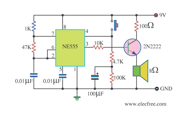
This is a danger beep circuit. It uses a 555 integrated circuit configured as a stable multivibrator that provides a duty cycle of 5% to drive a loudspeaker. The danger beep circuit utilizes the 555 timer IC, a versatile and...

A simple Sump Pump Control Circuit using NE555. The described circuit utilizes the NE555 timer integrated circuit (IC) to create a control system for a sump pump. The NE555 can be configured in various modes, but for this application, it...
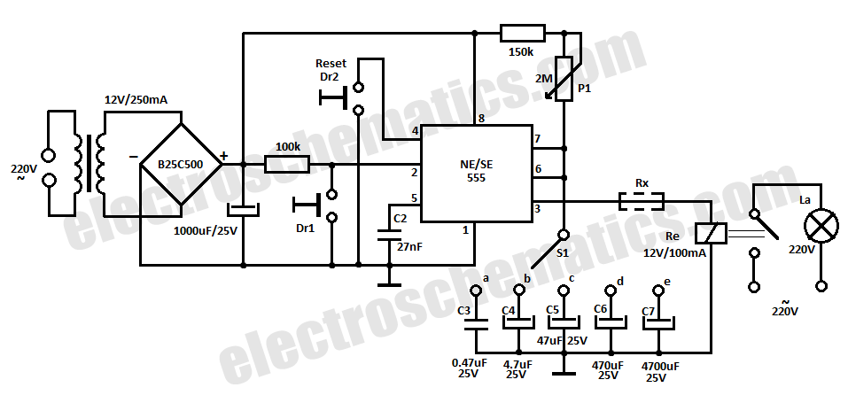
This time delay relay circuit is constructed using the NE/SE555 integrated circuit, manufactured by Intersil, which features a precision timer. The circuit exhibits stability against temperature variations. The NE/SE555 integrated circuit is a versatile timer used in various applications, including...
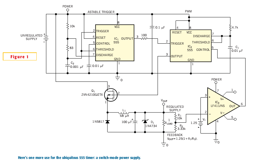
Most switch-mode power supplies utilize a PWM (pulse-width-modulated) output that is regulated through voltage feedback. A 555-timer IC can be used to generate PWM at a low cost. The circuit diagram illustrates how to convert a 555 PWM circuit...
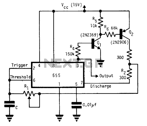
A single timing resistor ensures that the output is a square (50% duty cycle) wave at all frequency settings. Any 555 type of chip will do the job. The circuit utilizes a 555 timer IC configured in astable mode to...