
5hz to 500 Khz Frequency-Meter
The frequency meter design incorporates several essential components to enhance functionality and accuracy. The AT89C52 microcontroller serves as the core processing unit, executing counting algorithms and managing data display. The microcontroller's timer/counter features are leveraged to count input pulses accurately, with the timer configured to generate an interrupt every 1000 milliseconds, allowing for periodic frequency calculations.
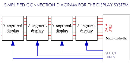
The display system utilizes four seven-segment displays configured to show numerical frequency readings. Each segment is driven by a dedicated output pin from the AT89C52, with multiplexing techniques employed to minimize the number of required connections while maintaining a clear and readable output. The use of averaging over the last five readings further stabilizes the displayed frequency, reducing the impact of transient fluctuations.
The input section of the frequency meter is designed to accept TTL-level signals, with appropriate protection circuitry to prevent damage to the microcontroller. The connections for P1 and P2 are designed to accommodate standard test leads, ensuring compatibility with various testing applications. The grounding scheme is critical; a common ground between the frequency meter and the device under test is essential for accurate measurements.
Power management is simplified through the use of the 7805 voltage regulator, which efficiently steps down the 9V battery supply to the 5V required by the AT89C52. This design choice eliminates the need for additional filtering components, as the low power consumption of the circuit minimizes electrical noise.
Overall, the frequency meter represents a compact and effective solution for frequency measurement in digital circuits, combining ease of use with reliable performance. The thoughtful integration of hardware components and user-friendly features ensures that this tool will be valuable for both hobbyists and professionals in the field of electronics.Based on the famous AT89C52 microcontroller, this 500 Khz frequency-Meter will be enough to trace and debug most of your circuits, to adjust 555 timers frequency and perform all kind of frequency measurements in Digital circuits. And once you have this tool between your hand, you will get used to it to the point of no-return! and you will say rem ember the days we adjusted the frequency by trial and error till we get it. ! To understand the block diagram below, you should recall the simplest definition of frequency: the number of occurrences within a given time period . What we are trying to do is to count the number of electric pulses during a time of one second. To do this we need a counter, to count the pulses, and a timer so that every 1000 milliseconds, the processor stop counting, calculate the frequency and display it, then start counting again from zero.
Below (figure 1) this is the principle of operation of a frequency meter, however, to build a reliable frequency meter, we will need to do some more mathematical operations. For example: Some operations will accurately predict the frequency before waiting for a whole second to elapse, which will also increase the refresh rate.
Another minor upgrade is to to display the average of the last 5 reading rather than displaying the frequency instantaneously (which can cause lot of display flickering if the frequency being measured is not very stable). Lets start by this easy part, to make the project look far-or-less like a profession lab equipment, well I simply built it in an old Avo-Meter, one of those you find in stores for less than $5!
(god bless china!), and then painted it all in black. (it was originally yellow!) and by the way, after I hacked that poor Avo-Meter, I also used the same leads for our frequency meter. As you can notice in the picture, there are four seven segments display. Finally you can also notice the two connections for the leads (Blue shaded area). Those connectors are standard for the test leads of most AVO meters and testing devices. Before Getting into the electronics, here is a final trick: To make the display look even neater and Protect it from dust and scratches, simply add a thin plastic film on top of it (it will be firmly held in its place when the frequency meter is re-assembled).
I am sure that you understand that to accomplish this project, we will need to perform some mathematical operations, as mentioned before, to increase the performance of the device. Thus we will rely on an AT89C52 microcontroller to perform all the required tasks in this project. While being very simple (as you can see in this diagram), the display system can seem complicated due to the high number of connections (as you can see in the schematic below).
Believe it or not, the human eye wont notice anything wrong, because, with the given delays the display will refresh at the rate of 375 cycles per second (375 Hz!) and the human eye can hardly notice some flickering in a display refreshing at 24 Hz. Nothing really critical about this part, since we only intend to measure TTL frequencies, the input is directly fed to the TO pin of the AT89C52, which will be used as a counter (more details about this in the software part).
P1 and P2 are simply the two connections for the test leads. Note that in order to make any kind of measurements on another circuit, the ground of the Measurement device and of the circuit being tested must be connected together, this is why there are at least two leads in any testing device (one for the Ground and one for the measured signal). The Power supply here is not critical either, because the device will be powered from a 9V alkaline battery, so we don`t need any filter capacitors, we just need to reduce 9V to 5V, and this is simply the job of the IC 7805 (Usually we add decoupling and filter capacitors when there is a lot of disturbance like in motor controllers, or AC to D
🔗 External reference
Related Circuits
The transmitter was designed with redundancy and cutback (reduced power mode) in mind, giving the transmitter more continuity of service. The final amplifier was divided into 3 separate modules, each using four RCA type UV-898 tubes in push-pull parallel...
Set R5 to read 1V RMS on an audio millivoltmeter connected to the output with R7 rotated fully clockwise, or to view a sine wave of 2.828V peak-to-peak amplitude on the oscilloscope. An audio amplifier is an electronic device...
This is a booster antenna circuit designed for frequencies ranging from 550 kHz to 1650 kHz, aimed at amplifying signals received from a telescopic antenna. It covers the medium waveband within this frequency range. To drive low impedance (50...
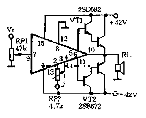
The AP500A amplifier offers numerous advantages, providing unmatched superiority in stereo applications. It can utilize various amplifier configurations, including OTI, CI, rK, BTL, class AB, and super CP. The typical DC amplifier module for the AP500A is illustrated in...
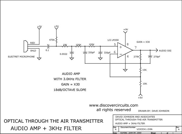
Audio amplifier with a 3 kHz filter. This circuit serves as the audio amplification section for a complete optical transmitter. It amplifies and filters voice audio signals from an electret microphone. The audio amplifier circuit is designed to enhance the...
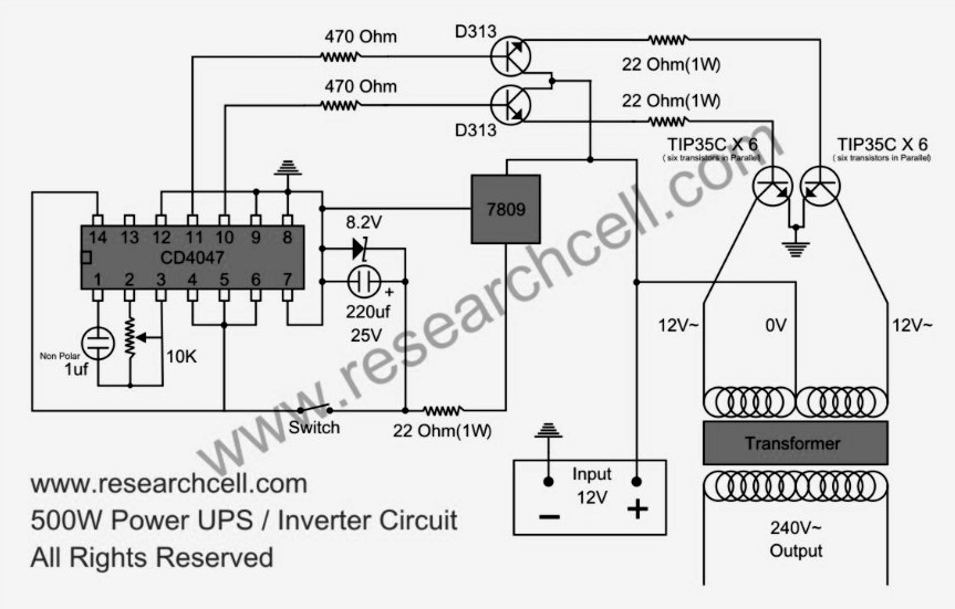
This circuit diagram features a single variable resistor utilized to adjust the frequency of a 240V AC output current. It is advisable to use a frequency meter to modify the frequency from 50Hz to 60Hz according to specific requirements....