
Negative Supply From Single Positive Supply
This circuit typically employs a charge pump or a voltage inverter configuration to create a negative voltage from the available positive supply. The design usually incorporates a switching element, such as a transistor or a dedicated IC, that alternately connects and disconnects the load to the supply. By utilizing capacitors in a specific arrangement, the circuit can effectively convert the positive voltage into a negative voltage.
For instance, a basic charge pump circuit might consist of a capacitor that is charged to the positive supply voltage and then switched to discharge into the output, creating a negative voltage potential. The switching can be accomplished using a diode or a MOSFET, depending on the specific requirements of the application, such as efficiency and response time.
Moreover, the circuit may include filtering components to smooth the output voltage and reduce ripple, ensuring that the negative voltage supplied to the op-amp is stable and reliable. Additionally, protection elements, such as diodes, may be integrated to prevent reverse polarity or overvoltage conditions that could damage the op-amp or other connected components.
In conclusion, this innovative circuit design provides a practical solution for utilizing op-amps in single-supply applications, significantly expanding their usability in various electronic systems.Opamps are very useful. But one of their major drawbacks is the requirement of a dual supply. This seriously limits their applications in fields where a dual supply is not affordable or not practicable. This circuit solves the problem to a certain extent. It provides a negative voltage from a single positive supply. 🔗 External reference
Related Circuits
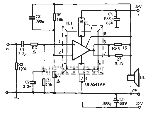
The Burr-Brown OPA541 chip is a power amplifier capable of operating with a maximum power supply voltage of 40V, delivering a continuous output current of up to 5A. The output current can be adjusted using an external resistor to...
This is a high-quality stabilized power supply circuit diagram. The output voltage can be adjusted from 0 volts to 30 volts DC, and the current output value can be adjusted from 0.002 A to 3 A. The circuit begins...
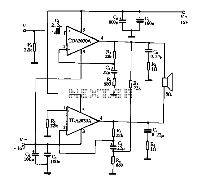
The 13TL amplifier utilizes discrete components and features a complex circuit structure. In contrast, the BTL amplifier circuit structure is simpler and generally performs well with fewer discrete components. Some integrated amplifiers, which are produced on a single integrated...
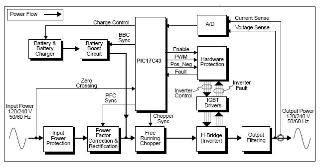
The UPS (Uninterruptible Power Supply) Reference Design offers a pre-designed uninterruptible power supply solution utilizing the flexibility of the PIC17C43 microcontroller. This microcontroller is noted for its low-cost and high-performance capabilities, which are not typically found in other microcontrollers....
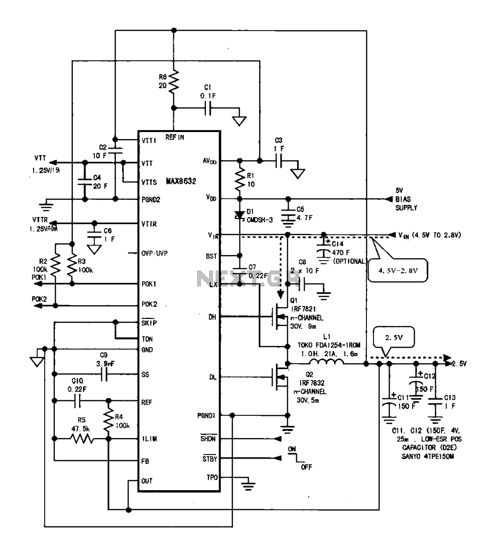
DDR memory power supply circuit. This circuit illustrates the power supply configuration for notebook DDR memory, utilizing the MAX8632 power control circuit chip. The power supply terminal VDD is connected to the voltage detection point 1. The battery DC...
A regulated voltage that can be adjusted to suit various applications is desired. This Adjustable Power Supply is compact, simple to construct, and can be modified to produce different output voltages. The Adjustable Power Supply circuit typically utilizes a linear...
Warning: include(partials/cookie-banner.php): Failed to open stream: Permission denied in /var/www/html/nextgr/view-circuit.php on line 713
Warning: include(): Failed opening 'partials/cookie-banner.php' for inclusion (include_path='.:/usr/share/php') in /var/www/html/nextgr/view-circuit.php on line 713