
5volt power supply
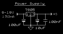
This circuit is designed to provide a stable +5V output suitable for various digital electronics applications. The core of the design is the 7805 voltage regulator, which is a linear voltage regulator capable of supplying a fixed output voltage of +5V. The input to this regulator requires an unregulated DC voltage in the range of 8 to 18V, which can be supplied by a small wall transformer. While these transformers are widely available, they often lack adequate voltage regulation, necessitating the use of the 7805 to ensure a stable output.
The circuit can initially deliver up to 150 mA of current, which is sufficient for many small-scale devices. However, with the addition of proper thermal management, such as a heatsink, the current output can be increased to 1A. This allows for greater flexibility in powering more demanding electronic components or circuits. The overload and thermal protection features integrated into the design safeguard the circuit from damage due to excessive current draw or overheating.
The components required for this circuit are commonly found in electronics shops, making it accessible for hobbyists and professionals alike. The design is based on a proven example from the 7805 datasheet, ensuring reliability and effectiveness in real-world applications. The circuit can be utilized in various contexts, including as a part of electronic devices or as a small laboratory power supply.
For modifications, if the application requires output currents exceeding 150 mA, it is recommended to select a transformer that can provide the necessary current. Additionally, the heatsink for the 7805 should be adequately sized to dissipate heat generated during operation, particularly at higher currents. For applications requiring different output voltages, the circuit can be adapted by substituting the 7805 with other regulators from the 78xx series, with the output voltage indicated by the last two digits of the regulator's part number. It is crucial to maintain an input voltage that is at least 3V higher than the desired output voltage to ensure proper regulation.This circuit is a small +5V power supply, which is useful when experimenting with digital electronics. Small inexpensive wall tranformers with variable output voltage are available from any electronics shop and supermarket.
Those transformers are easily available, but usually their voltage regulation is very poor, which makes then not very usable for digital circuit experimenter unless a better regulation can be achieved in some way. The following circuit is the answer to the problem. This circuit can give +5V output at about 150 mA current, but it can be increased to 1 A when good cooling is added to 7805 regulator chip.
The circuit has over overload and therminal protection. Circuit performance: Very stable +5V output voltage, reliable operation Availability of components: Easy to get, uses only very common basic components Design testing: Based on datasheet example circuit, I have used this circuit succesfully as part of many electronics projects Applications: Part of electronics devices, small laboratory power supply Power supply voltage: Unreglated DC 8-18V power supply Power supply current: Needed output current + 5 mA If you need more than 150 mA of output current, you can update the output current up to 1A doing the following modifications: Change the transformer from where you take the power to the circuit to a model which can give as much current as you need from output Put a heatsink to the 7805 regulator (so big that it does not overheat because of the extra losses in the regulator). If you need other voltages than +5V, you can modify the circuit by replacing the 7805 chips with another regulator with different output voltage from regulator 78xx chip family.
The last numbers in the the chip code tells the output voltage. Remember that the input voltage muts be at least 3V greater than regulator output voltage ot otherwise the regulator does not work well. 🔗 External reference
Related Circuits
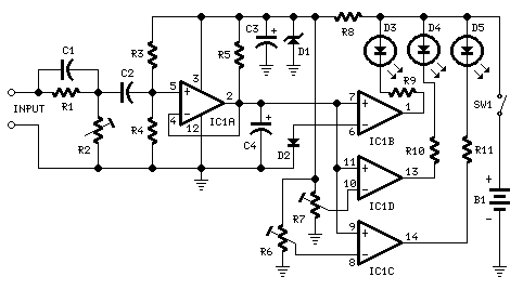
This circuit is intended to indicate the power output level of any audio amplifier. It is simple, portable, and displays three power levels that can be set to any desired value. IC1A is the input buffer, feeding 3 voltage...
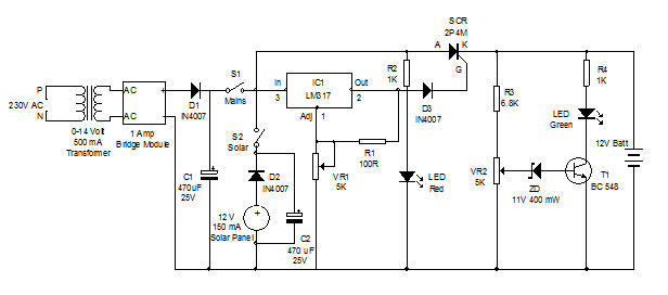
Battery charger utilizing solar and electrical power with a circuit diagram. This dual power source battery charger can charge a lead-acid battery using two different power sources. The battery charger circuit is designed to efficiently charge a lead-acid battery by...
This circuit allows for the measurement of the actual output power of an amplifier. It can be housed in a box to function as a measurement instrument. The circuit for measuring amplifier output power typically includes a few essential components:...
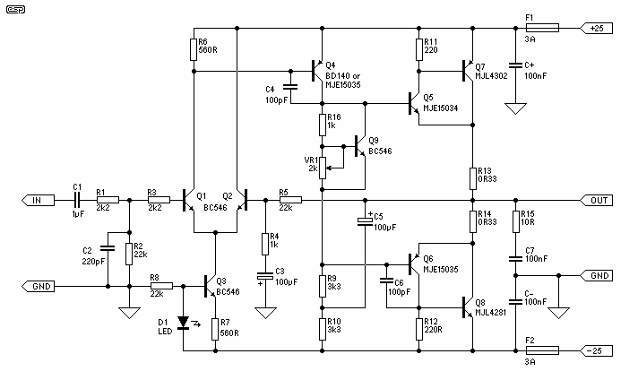
The basis for this amplifier has been around now for several years as Project 3A, and requires only relatively small modifications to be able to operate in Class-A. The biggest change is in output power (reduced dramatically from the 60-100W...
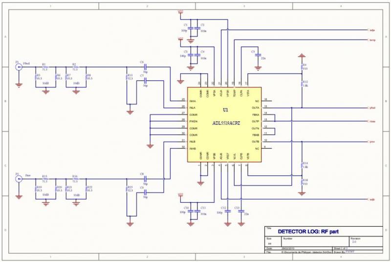
The ADL5519 is particularly focused on bandwidth, specified up to 8 GHz, though it remains usable at 10 GHz with reduced dynamic range. It features two channels, allowing for the measurement of power transmitted to the antenna and the...
The phone company provides 3 levels of power. With no devices 'off hook' the line rests at 48 volts DC. If you draw any more than a fraction of a milliamp or so, you get the phone company's attention...