
6 digit LED driver circuit
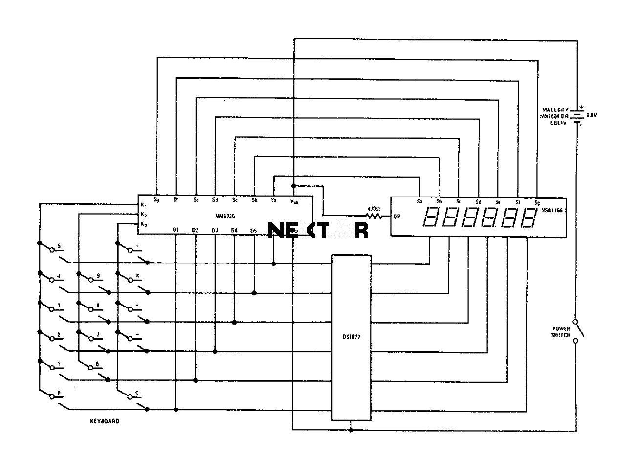
The DS8877 is a versatile driver integrated circuit designed for applications requiring control of display elements, such as in calculators. The circuit configuration involves connecting the DS8877 to a 6-digit display, allowing for the management of current flow between 5 mA and 50 mA, which is suitable for driving LED or LCD segments efficiently.
In this configuration, the DS8877 operates without the need for standby power, which enhances the overall efficiency of the system, particularly in battery-operated devices. The choice of operating voltage is flexible, accommodating 4.5V, 6V, or 9V sources, making the circuit adaptable to various power supply conditions. This flexibility is crucial for ensuring compatibility with different power sources and for optimizing performance across a range of applications.
The circuit design should incorporate appropriate resistors to limit the current to the display elements, ensuring that the current remains within the specified range. Additionally, decoupling capacitors may be included near the power supply pins of the DS8877 to stabilize the voltage and minimize noise, which is essential for maintaining the integrity of the displayed data.
In summary, the DS8877 drive circuit configuration is an efficient solution for controlling a 6-digit display in a compact form factor, with the flexibility of operating voltage and current range, making it suitable for a wide array of electronic devices.Configure National Semiconductors DS8877 drive circuit as shown, when the 6 digit calculator and digital current conjunction, the current range is 5 to 50mA. Drive does not req uire standby power, the operating voltage may be 4.5V, 6V, may be 9V.
Related Circuits
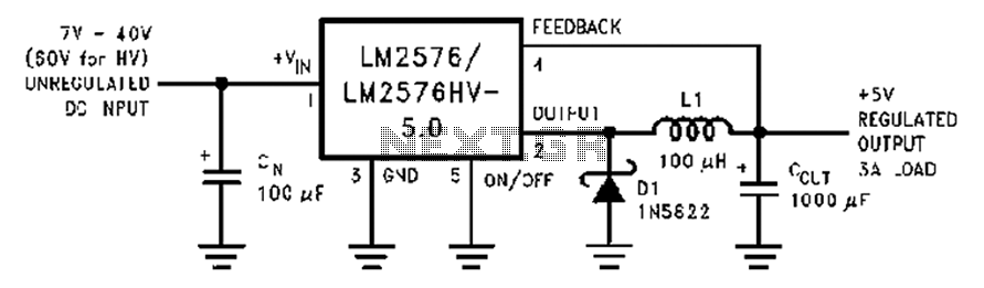
A wide range of 7 to 40V DC-DC step-down circuit that converts input voltage to 5V. This circuit operates as a buck converter, designed to efficiently reduce a higher DC voltage (ranging from 7V to 40V) to a stable output...
This circuit converts the analog signal from the reversed LED, which is in sensing mode, and amplified by the operational amplifier, into a digital (on/off) signal. The original complex design has been simplified. An alternative approach is discussed in...
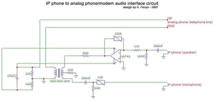
The transformer is a 600:600 ohm transformer, also referred to as a 1:1 ratio 600 ohm transformer. It has approximately the same number of turns on both the primary and secondary coils and is optimized for operation at a...
The circuit diagram of a TV antenna is sourced from the technical information provided by Chinaicmart. For more detailed information or additional circuit designs, further inquiry may be necessary. The circuit diagram for a TV antenna typically consists of several...
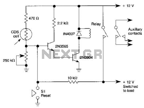
When light strikes the CDS cell, it activates the transistors, which in turn energizes the relay, causing it to latch. Pressing switch SI grounds the base of the 2N3565 transistor, thereby resetting the relay. Additionally, a 250 k potentiometer...
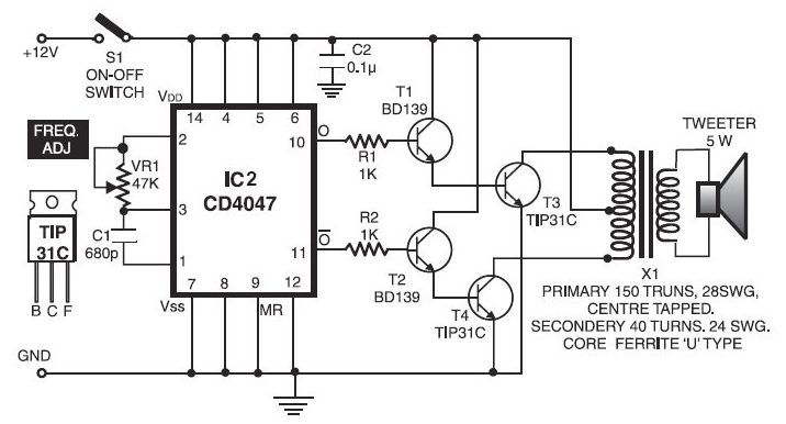
The electronic dog repellent circuit diagram below is a high-output ultrasonic transmitter primarily intended to act as a dog and cat repeller. The electronic dog repellent circuit utilizes a high-frequency ultrasonic transmitter to emit sound waves that are unpleasant to...
Warning: include(partials/cookie-banner.php): Failed to open stream: Permission denied in /var/www/html/nextgr/view-circuit.php on line 713
Warning: include(): Failed opening 'partials/cookie-banner.php' for inclusion (include_path='.:/usr/share/php') in /var/www/html/nextgr/view-circuit.php on line 713