
6A regulated variable powersupply
The described variable power supply schematic is designed to provide a versatile and adjustable output voltage, making it suitable for a wide range of applications. The use of a transformer (T1) allows for the conversion of high voltage AC mains to a lower AC voltage, which is subsequently rectified by the bridge rectifier (BR1) to produce a pulsating DC voltage. The inclusion of multiple resistors (R1, R2, R3, R4, R7, R8, R9) serves to control current flow and voltage levels throughout the circuit, ensuring stable operation.
The circuit's ability to deliver multiple regulated voltages (+12V, +5V, and -5V) is achieved through the careful selection of diodes (D1, D2, D3) and capacitors (C1, C2), which work together to smooth out the rectified voltage and provide reliable power to connected loads. The overvoltage protection ensured by the Zener diode (1N3997) and SCR (2N1595) is crucial for safeguarding sensitive components, particularly in applications involving integrated circuits that demand strict voltage tolerances.
Moreover, the adjustable output voltage ranging from 3V to 30V is made possible by the design of the regulator circuit, which allows for fine-tuning of the output based on the requirements of the connected devices. The incorporation of short circuit and overload protection features enhances the safety and reliability of the power supply, preventing damage to both the power supply and the connected load.
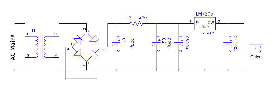
The battery charger circuit is particularly advantageous for applications involving NiCAD batteries, as it is designed to accommodate various configurations of battery cells. The series regulator configuration of power transistors (Q1 and Q2) is effective in managing the charging process, ensuring that the batteries are charged efficiently and safely. Overall, this schematic represents a comprehensive solution for power supply needs across various electronic applications.The following diagram is the schematic diagram of variable power supply which will deliver 0 to 28V output voltage at 6/8 A electric current. Component Part List: R1 = 2K2 Ohm 2, 5 Watt R2 = 240 Ohm R3, R4 = 0. 1 Ohm 10 Watt R7 = 6K8 Ohm R8 = 10K Ohm R9 = 47 Ohm. This is an adjustable power supply which have adjustabled output voltage from 6-12 DC v olt. Component Parts List: T1 = 115[220]/8 VAC transformer. Center Tap not needed. Q1 = 2N1613, NTE128, or substitute. (TO-39 case) On coolrib! BR1 = 40V, 4A. (Check max current of your mini-drill and add 2A) R1 = 470 ohm, 5%. This circuit generates 3 source regulated voltages applying a minimum of electronic parts. The output DC voltage are +12V ; +5V and -5V. Diodes D2 and D3 conduct full-wave rectification, at the same time charging capacitor C2 on each halves of the alternating current cycle. At the same time, diode D1 with capacitor C1, and. This is the circuit diagram of 5V Regulated Power Supply circuit, featured with over voltage protection.
The circuit is based regulator chip 7805; Thyristor SCR 2N1595 and Dioda Zener 1N3997 for overvoltage protection circuit. The 5V regulated power supply is apply 74LS series integrated circuits which has to be really precise and tolerant of voltage.
This is an adjustable and regulated power supply with 3V to 30V output voltage and supply up to 3A direct current. This circuit featured with short circuit protection and overload protection. Download the manual of this circuit include the schematic and part list HERE This battery charger circuit is regulated and adjustable to make this circuit able to charge the mosto NiCAD battery.
This circuit will work for single cell or multi battery cell which connected with series/parallel connection. The maximum voltage of the batteries should be 18V maximum. Power transistors Q1 and Q2 are connected as series regulators. 🔗 External reference
Related Circuits
A regulated 5-volt DC supply is essential for powering microcontroller and TTL-based circuits. The output of most wall adapters is often too rippled and impure for use in digital circuits. An inexpensive power supply can be constructed using discrete...
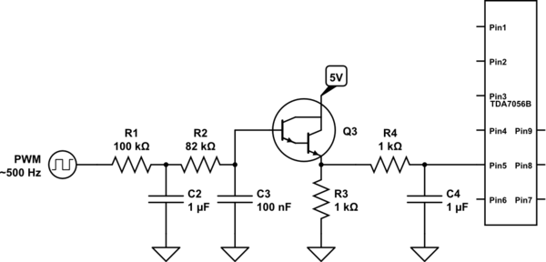
A voltage between 0.4 and 1.2 V is required on pin 5 to control the gain. In the initial two versions of the circuit, logic ICs and/or counters were utilized along with an operational amplifier and a resistor network...
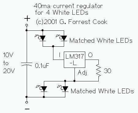
The LM317L and resistor act as a current regulator set to 40ma. Current flows from the battery through one pair of LEDs, through the regulator, through the other pair of LEDs, and back to the battery. The capacitor filters...
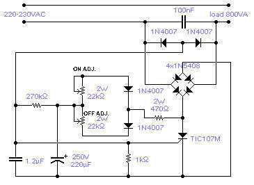
The circuit shown will switch on and off a resistive or inductive load up to 800VA with the possibility to adjust both the on and off period. Switching takes place during the zero crossing of the sine wave. The...
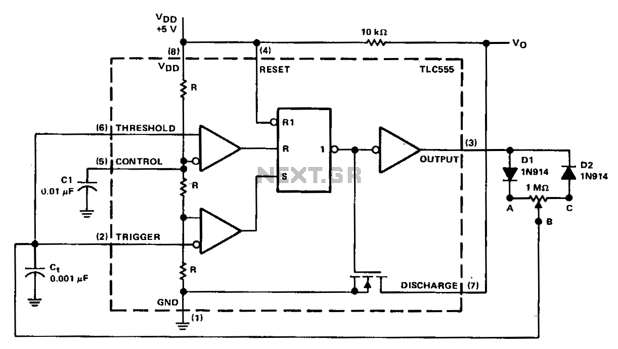
In a basic astable timer configuration, timing periods 11 and 12 are not independently controlled. This lack of control complicates the maintenance of a constant period, T, when either 11 or 12 is varied. In this circuit, the charge...
40V regulated power supply based on TIP42A and LM317. Refer to the specified page for an explanation of the related circuit diagram. The 40V regulated power supply utilizes a TIP42A transistor and an LM317 voltage regulator to provide a stable...