
7 2V Battery Replacement Power Supply For Camcorders
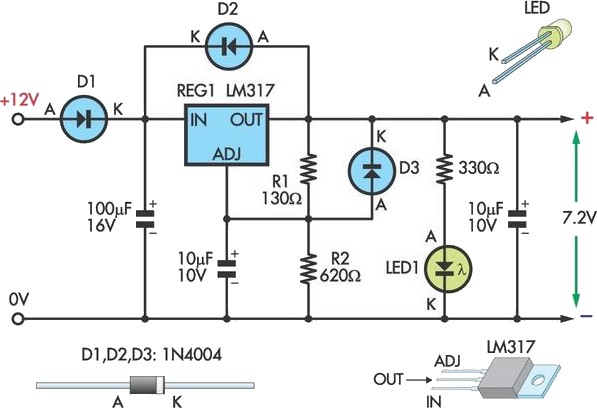
The circuit is designed to facilitate the use of a 12V sealed lead-acid (SLA) battery to power camcorders that originally operate on a 7.2V battery, providing a cost-effective alternative for users of older models. The core component of this design is the LM317 voltage regulator, which is renowned for its ability to deliver a stable output voltage that can be adjusted according to specific requirements.
In this configuration, resistors R1 and R2 play a crucial role in setting the output voltage to the desired 7.2V level. The output voltage can be calculated using the formula:
\[ V_{OUT} = V_{REF} \left(1 + \frac{R2}{R1}\right) \]
where \( V_{REF} \) is typically 1.25V. By adjusting the resistance values, users can fine-tune the output voltage to ensure compatibility with the camcorder. If the output voltage is found to be lower than expected, reducing the value of the 130-ohm resistor will increase the output voltage, while increasing its value will decrease the voltage.
For assembly, the circuit can be implemented on a variety of PC boards, with the Eliminator PC board being a recommended option due to its compatibility with the LM317 and the associated components. It is advisable to attach a heatsink to the LM317 to dissipate heat generated during operation, thereby enhancing reliability and performance.
Furthermore, the circuit's design includes a precautionary measure regarding battery management. To prevent the SLA battery from discharging due to the quiescent current drawn by the LED indicator and the voltage regulator when the circuit is not in use, it is essential to disconnect the circuit from the battery. This practice will prolong the life of the SLA battery and maintain its charge for when it is needed.
Overall, this circuit provides a practical solution for extending the usability of older camcorders while ensuring that the necessary voltage regulation is achieved efficiently.This circuit lets an external 12V SLA battery power a camcorder which normally has an inbuilt 7. 2V battery. Such batteries can now be very difficult or expensive to obtain for earlier model camcorders. In essence, the circuit is a standard LM317 adjustable regulator with resistors R1 & R2 set to provide 7. 2V (depending on the accuracy of the 1. 25V internal reference). If the resulting output voltage is low, it can be increased by reducing the 130 resistor and vice versa. The circuit can be assembled on to the Eliminator PC board or the simple DC power supply PC board. The regulator should be fitted with a flag heatsink. Note that the circuit should be disconnected from the battery when not in use, otherwise its quiescent current (from the LED and regulator) will flatten the SLA battery.
🔗 External reference
Related Circuits
The phone company provides 3 levels of power. With no devices 'off hook' the line rests at 48 volts DC. If you draw any more than a fraction of a milliamp or so, you get the phone company's attention...
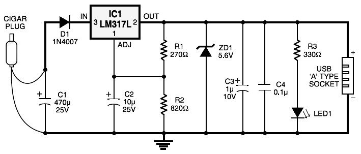
Cigar lighter plug to USB power socket. This circuit converts a 12V DC source from a car cigar lighter plug into a USB power socket with a 5V DC output. This circuit can be used to power 5V electronic...
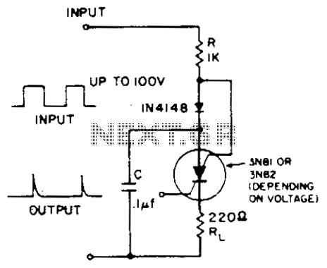
A positive-going input charges capacitor C through the IN4148 diode and resistor R. The diode ensures that the silicon-controlled switch (SCS) remains off. A negative-going input provides anode-gate current, which triggers the SCS, allowing capacitor C to discharge through...
Most amplifiers operate at acoustic frequencies, sometimes requiring two or even three transformers instead of a single power transformer. This approach is more prevalent in high-end amplifiers, where enthusiasts often prioritize high fidelity over cost. In these setups, the...
Iron the printed layout at a low heat setting until the ink adheres to the PCB. This process may take over an hour to complete. Afterward, remove the transparent paper. Next, submerge the PCB in Ferric Chloride solution until...
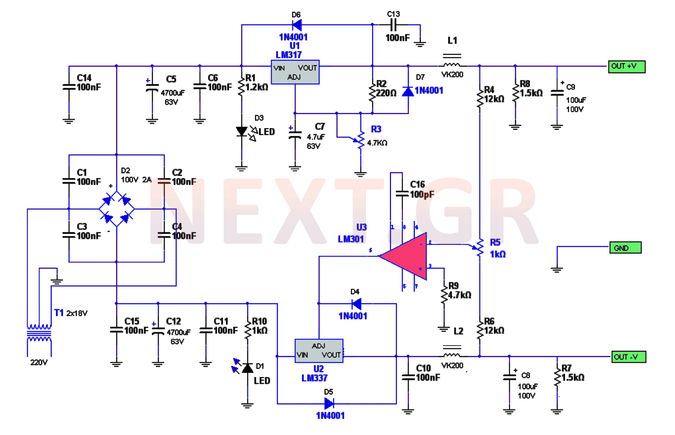
The power supply circuitry includes a 220/2 * 18V / 3.5A transformer, a rectifier, a smoothing filter, a power amplifier (LM301), and two regulators (LM317 and LM337). The voltage from the transformer is rectified by a bridge rectifier. Capacitors...
Warning: include(partials/cookie-banner.php): Failed to open stream: Permission denied in /var/www/html/nextgr/view-circuit.php on line 713
Warning: include(): Failed opening 'partials/cookie-banner.php' for inclusion (include_path='.:/usr/share/php') in /var/www/html/nextgr/view-circuit.php on line 713