
Simple dimming lights circuit diagram
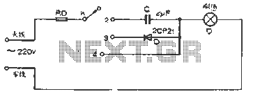
This circuit employs a multi-speed control switch to adjust the brightness of a connected lamp through various operational modes. The switch K allows for four distinct settings, each altering the electrical characteristics supplied to the lamp.
In position "1," the circuit is open, effectively disconnecting the power supply from the lamp and resulting in no light output. This position is useful for completely turning off the lamp without needing to unplug it.
Position "2" introduces a capacitive coupling, which allows a small amount of current to pass through, creating a shimmering light effect. This is achieved by using a capacitor in series with the lamp, which charges and discharges, providing an alternating current (AC) effect that gives the lamp a flickering appearance. This setting can be particularly useful for decorative lighting or ambiance.
In position "3," the circuit employs a diode for half-wave rectification. The diode permits current to flow in only one direction, effectively reducing the power supplied to the lamp to about 50% of its rated value. This results in a dimmer light output, suitable for situations where less brightness is desired while still maintaining a steady light without flickering.
Position "4" connects the lamp directly to the power supply at its rated voltage, allowing it to operate at full brightness. This configuration is ideal for scenarios requiring maximum illumination, such as in workspaces or areas needing bright lighting.
Overall, this dimming circuit provides versatility in light control, allowing users to select the desired brightness level according to their needs. The use of capacitive coupling and rectification techniques ensures that different light effects can be achieved while maintaining simplicity in the circuit design.The figure is a simple dimming lights line, the light is adjusted by the multi-speed control switch K. When K to position "1" lights out; when K to position "2", the light shimmering through the capacitive connection; when K to position "3", the half-wave rectified by the diode power to the lamp power supply, lamp brightness about half the usual; when K to position "4", the lamp at rated voltage, the brightness of the brightest.
Related Circuits
Thank you for your responses to my previous thread. I appreciate it. Please advise on how to convert a 24V DC and what circuit diagram should be used. To convert a 24V DC supply to a different voltage level, several...
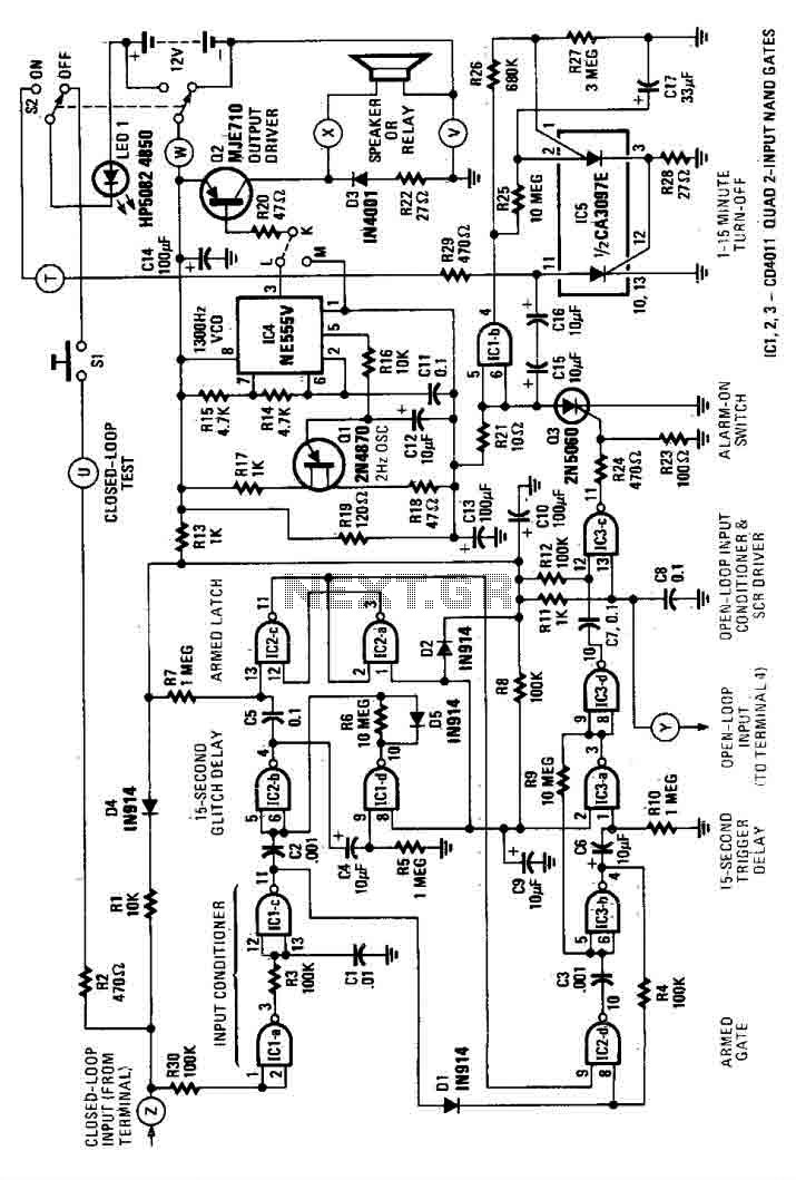
This house alarm circuit features both open and closed loop sensors and includes a self-shutdown function. The delay after triggering can be adjusted between 1 minute and 12 minutes, while the delay before triggering is set at 13 seconds....
This solid-state push-pull single-ended Class A circuit is designed to deliver sound quality comparable to valve amplifiers, providing an output power of 6.9W measured across an 8 Ohm loudspeaker cabinet load. It features reduced total harmonic distortion (THD), increased...
PWM waveforms are widely utilized to regulate the speed of DC motors. The duty cycle of the digital waveform can be established either through an adjustable analog voltage level (as seen in a NE555-based PWM generator) or through digital...

A VU (Volume Unit) meter has traditionally been a key component of audio metering systems. The Peak Program Meter (PPM) is known for its inadequacy in accurately displaying peak signal levels. This circuit serves the same function as previously...
Humidity detector circuit electronic project using common electronic parts The humidity detector circuit is a project designed to measure and indicate the level of humidity in the environment. This circuit utilizes commonly available electronic components, making it accessible for hobbyists...