
A regenerative SW receiver with automatic regeneration control
The tuned radio frequency (TRF) receiver circuit is designed to operate optimally within the 25-meter shortwave band, utilizing a resonant tank circuit that incorporates a loop antenna and several capacitors. The loop antenna, constructed with copper wire, is critical for achieving high sensitivity and selectivity, allowing the receiver to capture weak signals effectively. The choice of components, including low-noise RF transistors and precision capacitors, is essential for minimizing noise and maximizing the quality factor (Q) of the resonant circuit.
The automatic regeneration control circuit is a key feature, enhancing the receiver's ability to maintain stable operation while amplifying incoming signals. The use of a diode detector facilitates the demodulation of the received signals, converting them into a usable audio frequency for headphones. The audio amplifier stage is designed to provide sufficient power to drive the headphones, ensuring clear audio output.
The construction of the loop antenna is particularly important, as its dimensions and winding characteristics directly influence the receiver's performance. The design allows for adjustments in capacitance to optimize tuning, and the inclusion of a trimmer capacitor provides fine-tuning capabilities. However, the design does have limitations, such as sensitivity to nearby objects and supply voltage variations, which can affect the regenerative stage's performance.
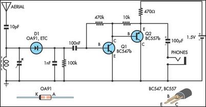
Overall, this TRF receiver design offers a robust platform for shortwave radio experimentation, with opportunities for further enhancements and modifications to improve performance and adaptability in various operating conditions.This is the tuned radio frequency receiver for shortwave (25 meter band, 11. 7. 12. 1 MHz). It was created as experimental design for further experiments with the autodyne synchronous receiver (see Polyakov V. T. Autodyne synchronous regenerative receiver. - Radio, 1994, N 3, page. 10. ). The circuit diagram is shown in Figure 1. The input resonant t ank composed of the loop antenna WA1 and capacitors C6 (the trimmer capacitor), C7 (the variable capacitor), C8 and C9. The resonant tank circuit has very high quality factor Q within the working band (11. 7. 12. 1 MHz), so the effective height of the loop antenna can be up to several tens of meters. An antenna with this parameters can receive very weak signals. The sensitivity of this shortwave receiver is limited by the noise of the transistor VT1, so it would be better to use in the first stage a low-noise RF transistor.
The automatic regeneration control circuit includes the second stage of HF amplifier (the transistor VT2) and the diode based detector (C11, VD1, VD2, C13). The resistors R1, R2 and R6 provide a bias current for diodes VD1, VD2 and for the transistor VT1. From the output of the detector the DC signal corrects the regeneration of the regenerative stage, the AC component of signal goes through the capacitor C12 to the one-stage audio amplifier based on the transistor VT3.
The headphones BF1 is the load of this audio amplifier. The resistance of the headphones is about 1600. 3200 ohms. The output power of the audio amplifier is about 1 milliwatt. The resistor R4 provides a feedback biasing for the transistor VT2, and the resistor R9 does the same for the transistor VT3. Match the resistor R4 to get the voltage across the collector of the transistor VT2 equals to half of the supply voltage.
The coil of the loop antenna WA1 is frameless with a diameter of 200 mm, it consists of 2 turns of copper wire 1. 5 mm (AWG 15), the step of the winding is 10 mm. To make the loop antenna rigid, we can fix the turns with each other with pieces of dielectric material.
The antenna can be made out of a ferrite rod, but it would work much worse. The variable capacitor C7 can be used with larger capacitance, for example, 4. 200 pF, but it requires a small ceramic capacitor 15. 25 pF connected in series with C7. A varicap can be used for tuning, but it will reduce the quality factor Q of the resonant tank circuit, and the varicap will require an additional voltage source of 15. 25 V. Setup the regenerative stage on the edge of oscillation by matching value of the capacitor C10 and by adjusting the trimming potentiometer R8.
This potentiometer should be high quality, else its noise will interfere with the receiver. If you haven`t a high quality potentiometer, you can replace it with a resistor (match its value). Use the trimmer capacitor C6 to adjust the frequency band of the receiver. There are two shortages in this regenerative receiver - the tuning of the regenerative stage is depends on the supply voltage, and if there is a massive object in vicinity of the loop antenna, its quality factor goes down. The reception quality of this radio receiver is better than a superheterodyne radio receiver because of the narrow band, the directional properties of the loop antenna, and total absence of an image frequency interference.
But this advantages are useless when there is a powerful radio signal in the working frequency range. 🔗 External reference
Related Circuits
This circuit is essentially an amplified crystal set. The inductor could be a standard AM radio ferrite rod antenna while the tuning capacitor is a variable one. The described circuit operates as an amplified crystal radio receiver, which utilizes a...
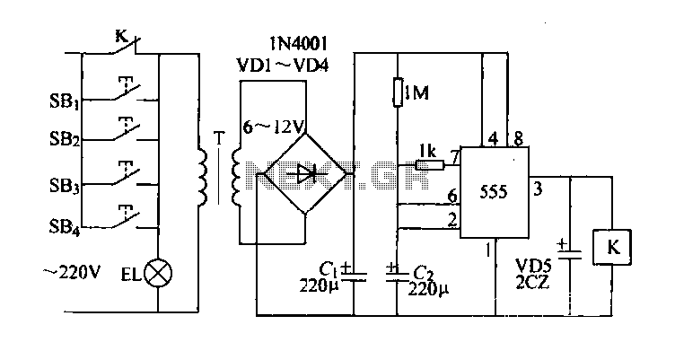
Control buttons SB1 to SB4 can be installed in various positions within a corridor. By pressing any one of these buttons, the EL horse lights will turn on. After releasing the button, the transformer and rectifier supply power to...
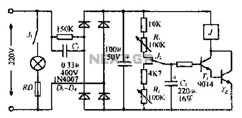
220V mains electricity is sent through a 0.33 µF capacitor (Ci) and a 50 kΩ resistive drop. A bridge rectifier composed of diodes D1 to D4 converts the AC voltage to DC. After passing through a 100 µF capacitor...
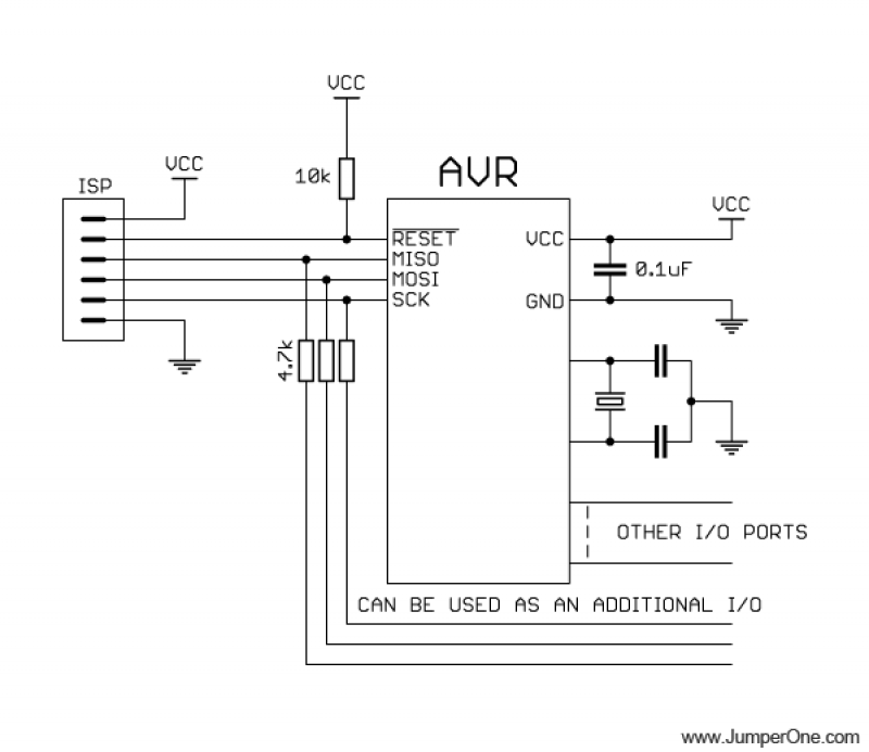
This schematic illustrates the placement of a decoupling capacitor on the right side, which should be positioned as close as possible to the power pins of the microcontroller. It includes a crystal oscillator, which is optional; an internal RC...
Automatic fan control circuit. This circuit turns a 12V DC fan or CPU fan on or off based on temperature readings. The temperature can be adjusted using VR1. The automatic fan control circuit operates by monitoring the temperature of...
The following circuit illustrates a Railway Turnout Control Circuit Diagram. Features include a logic level in the range of 5 to 12 V, utilized for controlling model railways. The Railway Turnout Control Circuit is designed to manage the switching of...