
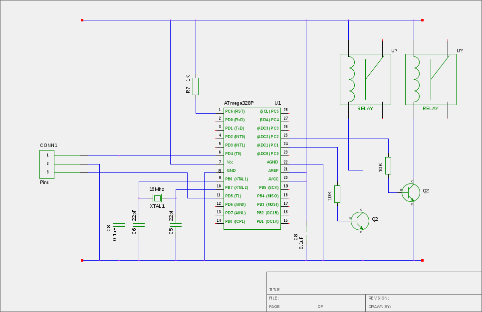
Railway Turnout Control

The Railway Turnout Control Circuit is designed to manage the switching of railway tracks, commonly referred to as turnouts or switches, in model railway systems. This circuit typically operates within a logic voltage range of 5 to 12 volts, making it suitable for interfacing with various control systems and components commonly found in model railroading.
The circuit usually consists of a microcontroller or logic IC that generates the control signals necessary to actuate the turnout mechanism. The control signals are sent to a relay or a transistor switch, which in turn powers the turnout motor or actuator. The design may also incorporate feedback mechanisms, such as limit switches, to confirm the position of the turnout, ensuring accurate operation.
Additional features may include LED indicators to show the status of the turnout, as well as protection components such as diodes to prevent back EMF from damaging the control circuitry. The circuit can be expanded to include multiple turnouts and can be integrated with more complex control systems, such as those utilizing digital command control (DCC) protocols, allowing for sophisticated operation and automation of model railway layouts.
In summary, the Railway Turnout Control Circuit is a crucial component for model railway enthusiasts, providing reliable and efficient control over track switching, enhancing the overall functionality and enjoyment of the railway system.escriptipn: The following circuit shows about Railway Turnout Control Circuit Diagram. Features: logic level in the range of 512 V, used to control model .. 🔗 External reference
Related Circuits
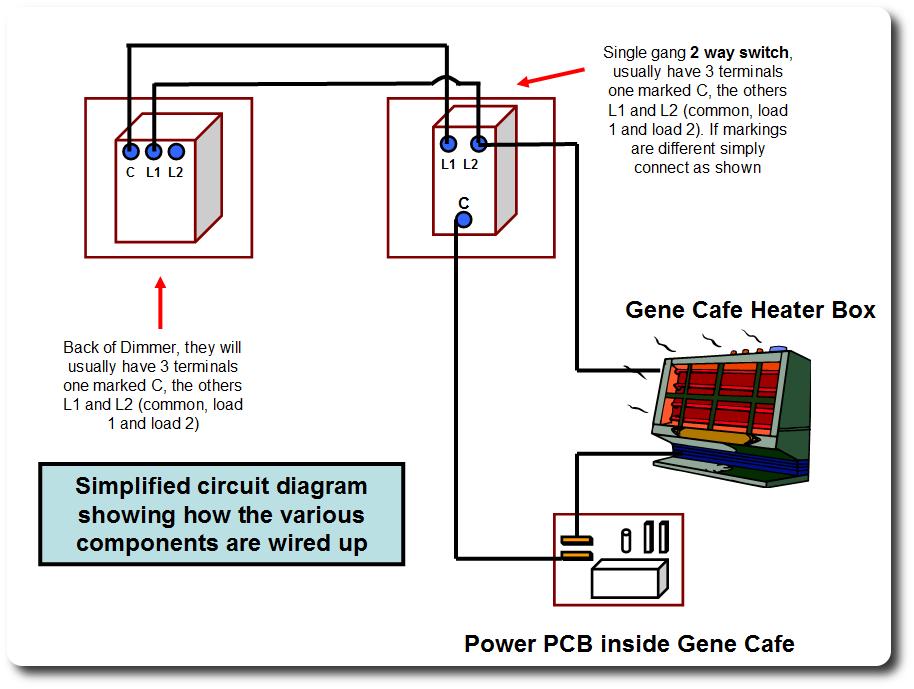
Enable the Gene to progressively lower the power applied to the heating element, allowing it to reduce heat instead of switching on and off. This minimizes the temperature gradient within the drum and the maximum temperatures that the beans...
If a Squeezebox is present, it is likely accompanied by an amplifier. The inconvenience of manually turning the amplifier on and off, especially when the Squeezebox is stored in a cupboard, necessitates a device that automatically powers the amplifier...
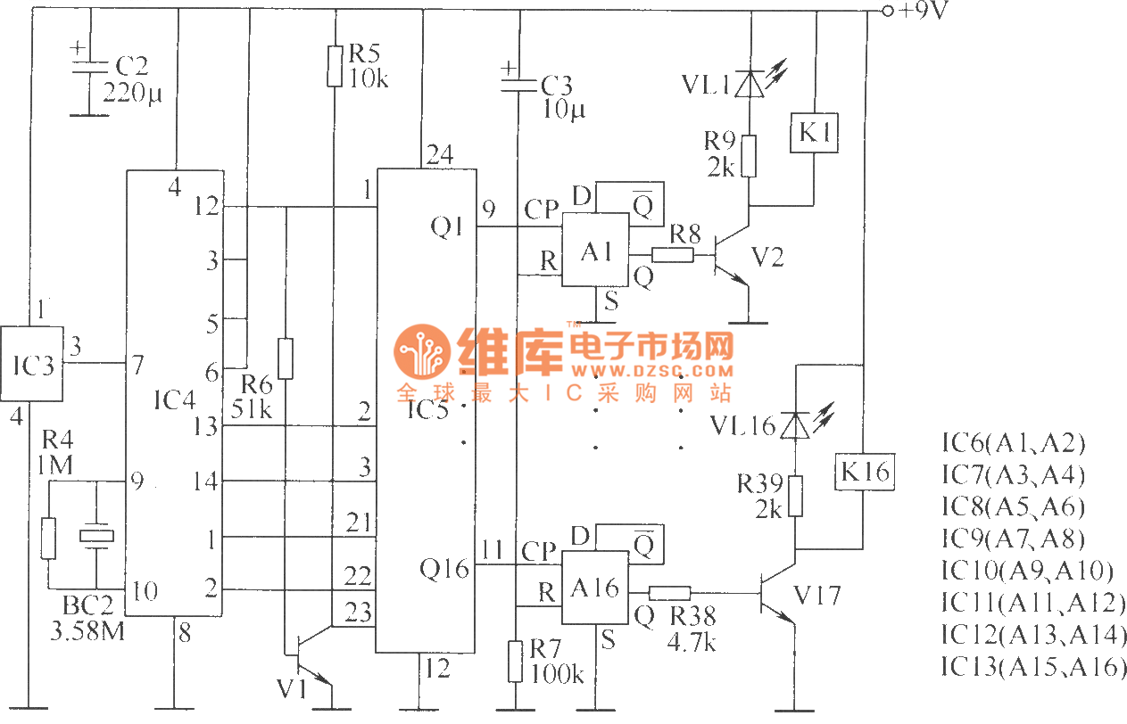
The wireless remote control transmitter circuit consists of control buttons S1 to S16, resistors R1 to R3, a capacitor C1, a regulator diode VS, a crystal oscillator BC1, and DTMF encoder integrated circuits IC1 and IC2. The circuit components...
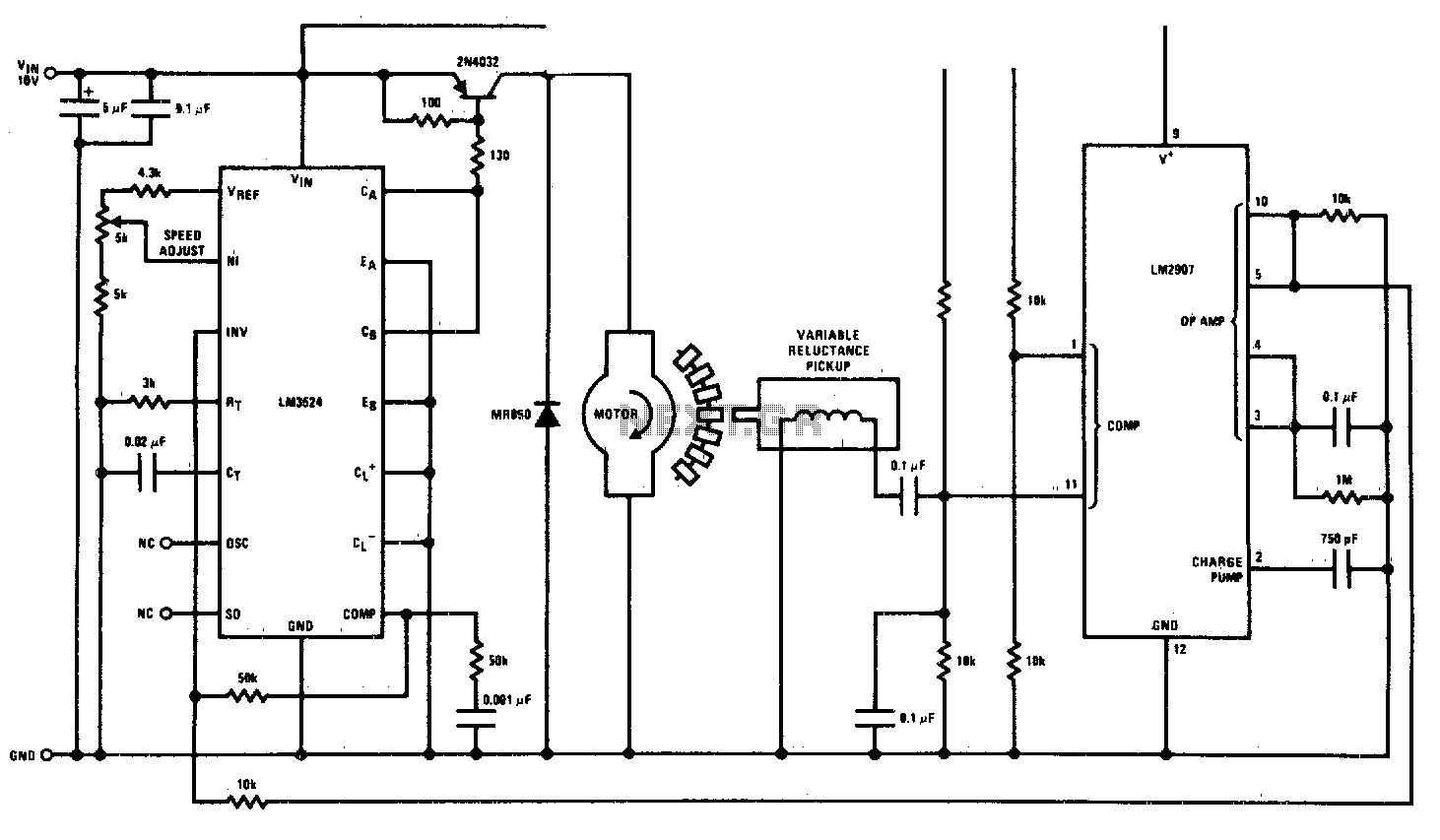
This circuit is a regulating series DC motor speed control using the LM3524 for the control and drive of the motor and the LM2907 as a speed sensor for the feedback network. The circuit employs the LM3524 integrated circuit, which...
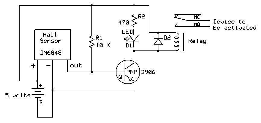
A sensor used in garden railway applications, Hall Effect sensors are the electronic equivalent of a reed switch. They can be thought of as a combination of a reed switch and a transistor. These sensors are commonly employed to...
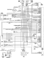
The electrical wiring diagram for the 1993 VW Passat includes the Engine Control Module, Automatic Control Unit, and Automatic Solenoid. This diagram illustrates the connections and wiring between various components of the vehicle's system, such as the multi-function switch,...