
AC bridge using LF356
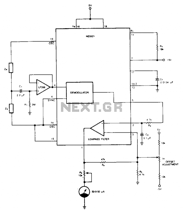
The circuit design is based on a half-bridge configuration that effectively balances the impedances ZR and Zx. The differential excitation provided by the OSC signals helps to enhance the sensitivity of the measurement. The LF356 op-amp is chosen for its FET input characteristics, providing high input impedance and low bias currents, which is crucial for accurate impedance matching and measurement, especially in sensitive applications.
Capacitor CI plays a vital role in AC coupling, ensuring that any DC offset present does not interfere with the AC signals being analyzed. This is particularly important in precision measurement applications where the integrity of the AC signal is paramount. Resistor Rl is strategically placed to maintain the output of the LF356 at 0 V under DC conditions, thus preventing any unwanted DC offsets from affecting the measurement accuracy.
The AC output from the demodulator is subjected to filtering through the uncommitted amplifier, which smooths out the signal and converts it into a usable DC voltage for the meter. The inclusion of the 10 kΩ potentiometer (R5) is a safety feature that protects the meter from excessive current, ensuring the longevity and reliability of the measurement system.
Calibration is a critical step in the operation of this circuit. By initially matching impedances at ZR and Zx, the system can be accurately zeroed out, allowing for precise measurements of unknown impedances thereafter. The process of adjusting the offset ensures that the readings are accurate, and the subsequent calibration with known values allows for the fine-tuning of the system to achieve the specified accuracy of ±0.05%.
Overall, this circuit provides a robust solution for impedance measurement, combining cost-effectiveness with high precision, making it suitable for a range of applications in electronics testing and analysis.The circuit provides a simple and cost-effective solution to matching resistors and capacitors. Impedances ZR and Zx form a half-bridge, while OSC and OSC excite the bridge differentially. The external op amp is a FET input amplifier (LF356) with very low input bias current on the order of 30 pA (typical). CI allows ac coupling by blocking the dc common mode voltage from the bridge, while Rl biases the output of LF356 to 0 V at dc.
Use of FET input op amp insures that dc offset due to bias current through Rl is negligible. Ac output of the demodulator is filtered via the uncommitted amp to provide dc voltage for the meter. The 10 k potentiometer, R5, limits the current into the meter to a safe level. Calibration begins by placing equal impedances at ZR and Zx, and the system offset is nulled by the offset adjust circuit so that Pin 1 is at 0 V.
Next, known values are placed at Zx and the meter deviations are calibrated. The bridge is now ready to measure an unknown impedance at Zx with ±0.05% accuracy or better. 🔗 External reference
Related Circuits
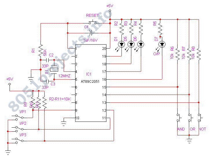
This project Digital gated Emulator using Microcontroller is used to emulate the basic gates such us NOT, OR, AND. The system has the selector switch by which we can select any gate. The system has two inputs and one...
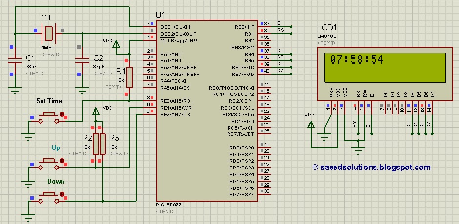
This tutorial on the PIC16F877 microcontroller addresses the question, "How to implement a controllable digital clock using the PIC16F877?" It utilizes the PIC16 simulator for demonstration purposes. The implementation of a controllable digital clock using the PIC16F877 microcontroller involves several...
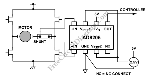
A differential current sensing circuit is integrated within an H-bridge configuration, as illustrated in the schematic diagram below. This circuit exemplifies the application of the AD8205, which is capable of measuring current in both directions as the motor changes...
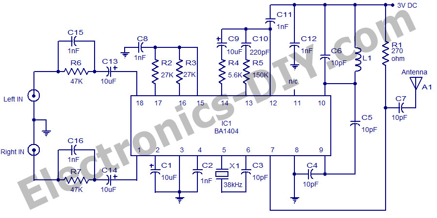
A high-quality stereo FM transmitter circuit is presented here. The circuit utilizes the IC BA1404 from ROHM Semiconductors. The BA1404 is a monolithic FM stereo modulator that incorporates a built-in stereo modulator, FM modulator, and RF amplifier circuitry. The...
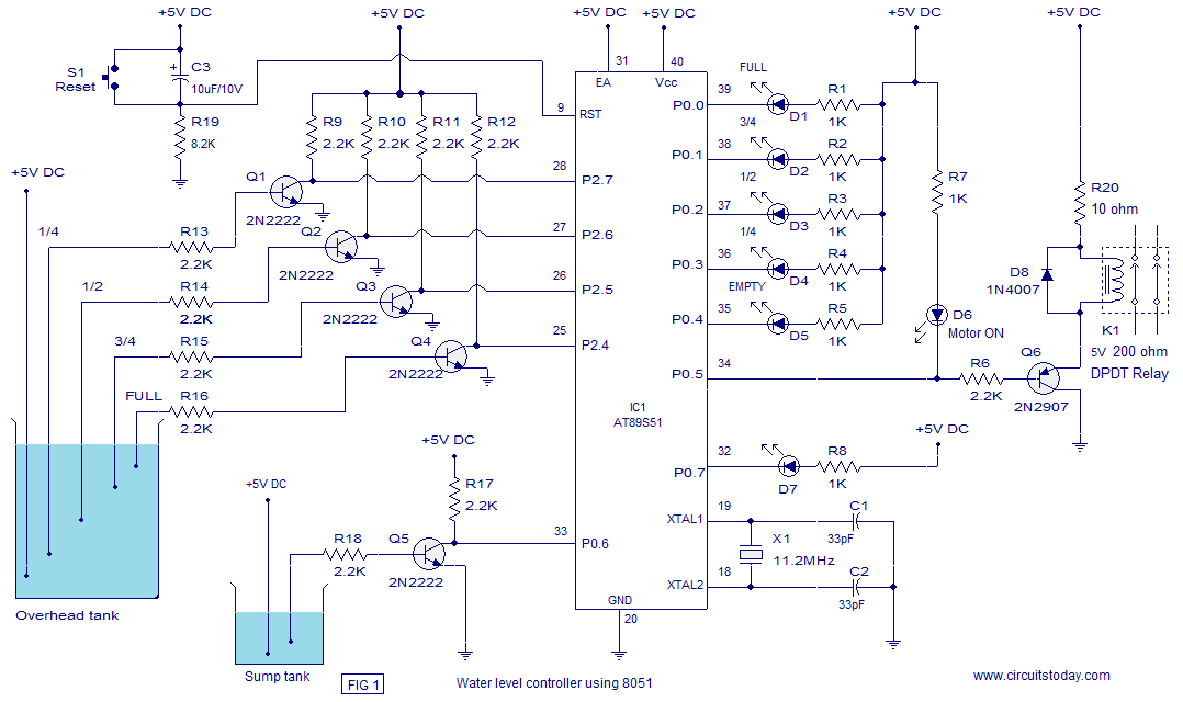
A water level controller based on the 8051 microcontroller is presented in this article. While numerous water level controller projects have been published on this website, this is the first one utilizing a microcontroller. The water level controller monitors...
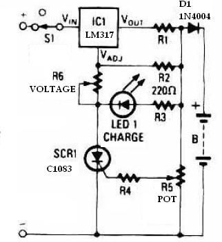
This schematic circuit for a battery charger consists of very few components but operates effectively. When power is applied to the circuit, SCR1 remains off, preventing any bias current from flowing to ground. The LM317 voltage regulator is connected...