
ac power control with thyristor
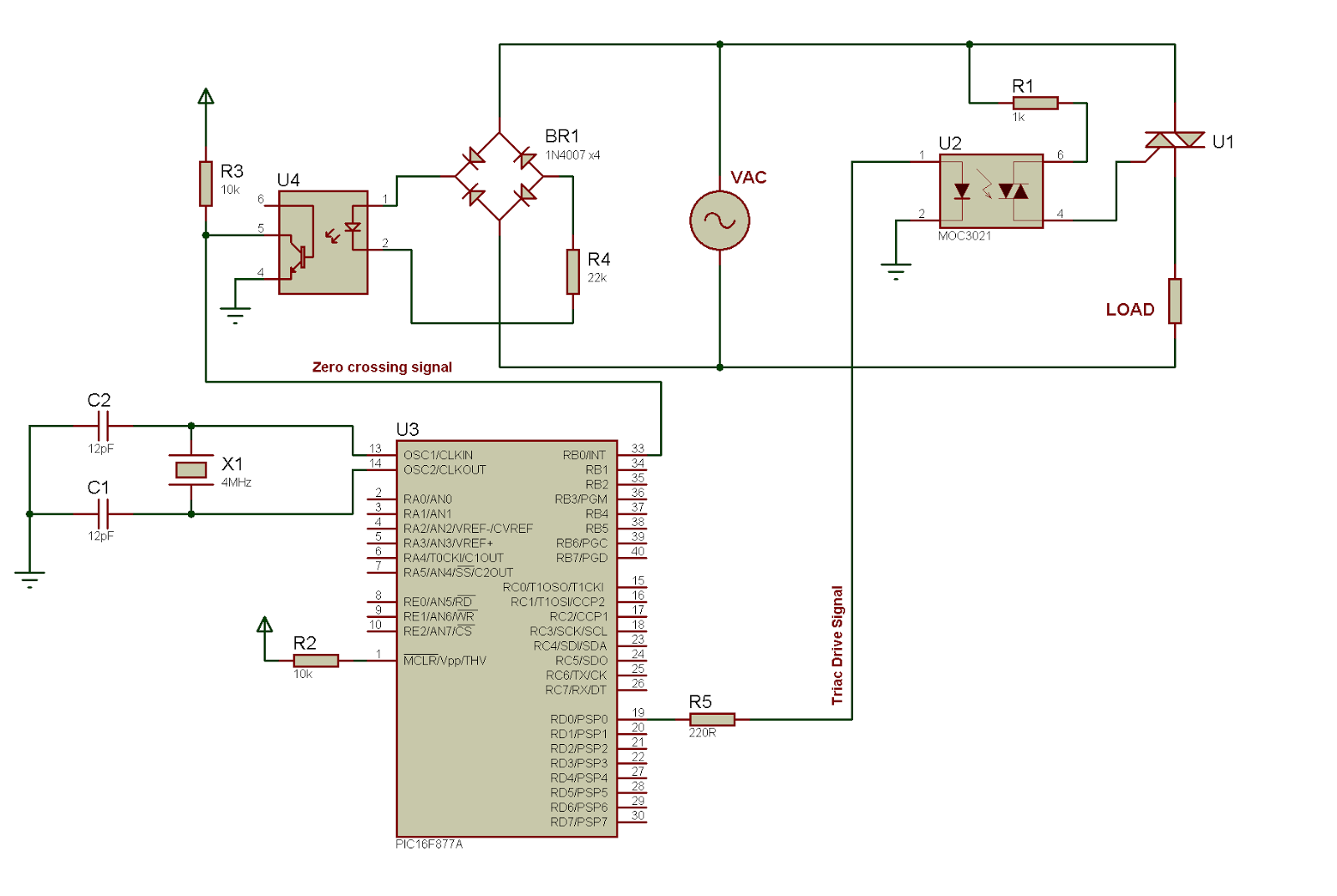
Phase angle control is a sophisticated method of managing AC power delivery. In practical applications, the circuit typically consists of a triac connected in series with the load, and a control circuit that generates the gating signal based on the desired phase angle. The control circuit often includes a zero-crossing detector, which identifies when the AC voltage waveform crosses zero volts. This detector is crucial as it provides a reference point for timing the gating signal.
The timing of the gating pulse is critical; it determines the phase angle at which the triac is triggered. By adjusting this timing, the average power delivered to the load can be finely controlled. The relationship between the phase angle and the RMS voltage can be complex, particularly in non-linear loads, and requires careful consideration in design.
In addition to resistive loads like incandescent bulbs, phase angle control can also be applied to inductive loads, though this introduces additional complexities such as phase shift and back EMF effects. For inductive loads, the effective power delivered may differ from the calculated power due to these factors, necessitating more sophisticated control strategies.
Simulation tools can be employed to model the behavior of phase angle control circuits, allowing engineers to visualize the effects of different firing angles on the output voltage and current waveforms. This modeling is invaluable for optimizing circuit performance before physical implementation.
In conclusion, phase angle control is an essential technique in power electronics, enabling efficient management of AC power to various types of loads. Its implementation requires a thorough understanding of thyristor operation, load characteristics, and the dynamics of AC waveforms.The photo above clearly illustrates phase angle control: output voltage controlled by the gate drive signal applied to a thyristor. What is phase angle control That is what I`m going to talk about in this article. Phase angle control is a method of PWM applied to AC input voltages, usually the mains supply. Of course, the AC supply could be from a transformer or any other AC source, but the mains supply is the most common input this gives the phase angle control method its greatest usefulness. It has of course become quite obvious from the title (and I`m sure most of you reading will already know this) that the purpose of phase angle control is to control or limit power to the load.
The power device used in phase angle controllers is a thyristor mostly triacs or SCRs. (There are methods of phase controlling employing high frequency switching using a MOSFET or IGBT, but here I`ll talk about phase angle control with thyristors only). The power flow to the load is controlled by delaying the firing angle (firing time each half-cycle) to the power device.
We know that the thyristor is a latching device when the thyristor is turned on by a gating signal and the current is higher than the holding current and the latching current, the thyristor stays on, until the current through it becomes sufficiently low (very close to zero). The thyristor turns off when current through it becomes zero, as happens at the AC mains zero crossing.
This is the natural line commutation. (Another method of turning the thyristor off is by forced commutation. I won`t go into that now. ) The assumption here is that the load is resistive and has little to no inductance. Of course, this is not always the case, as inductive loads are often used. However, I`ll work with this assumption for now. I`ve added the circuit, code and simulation of an example later in this article. And that uses a triac as the power device. So, from now on, I`ll just refer to the triac instead of talking about a thyristor in general. So, in phase angle control, a gate pulse is sent to the triac. This is sent at a time between one zero crossing and the next. Without the gate pulse sent to the triac, right after zero-crossing, the triac is off and no current flows through it. After a certain time, the gating signal is given to the triac and it turns on. The triac then stays on until the current through it becomes zero (natural line commutation). This is at the next zero crossing. For simplicity`s sake and as usually should be, assume that the current through the triac (when on) is larger than the latching current and the holding current.
If you didn`t already know this, the latching current is the current that must pass through the triac right after it is turned on to ensure that it latches. The holding current is the current level through the triac below which the triac will turn off. So, the assumption that current through the triac is higher than the latching current and the holding current means that the triac stays on once it is fired on.
It stays on until the current through it is zero. This means that the voltage is supplied to the load for a fraction of the cycle, determined by how long the triac is on. How long the triac is on, is, in turn, determined by the delay time between the zero-crossing and the applying of the triac gating signal.
So, to sum it up, we adjust the voltage or power delivered to the load by delaying the trigger signal to the triac. One thing to remember is that, the delivered voltage and power are not linearly related to the firing phase angle.
There are two voltages here that we are concerned with the RMS voltage and the average voltage. The RMS voltage governs the power output to resistive loads such as incandescent bulbs and resistive heaters. The average value relates to devices that function on the average voltage level. This is important because, when testing, your voltmeter will register 🔗 External reference
Related Circuits
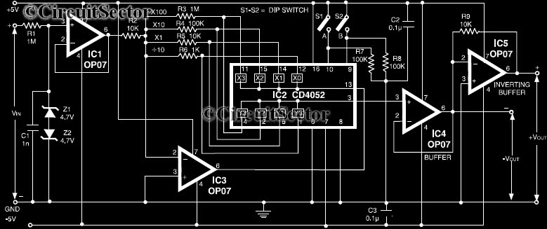
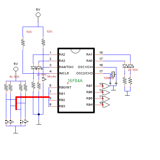
This circuit is a precision amplifier with digital control, designed for signal conditioning of low-output transducers operating in the millivolt range. The resistors R3 to R6 can be user-selected, with values ranging from 1 kilo-ohm to 1 mega-ohm, allowing...
This document contains a collection of schematic diagrams, datasheets, images, and tips for switch mode power supplies (SMPS) utilizing the TL494, LM339, KA7500, and IC2003 integrated circuits. Switch Mode Power Supplies (SMPS) are crucial components in modern electronic devices, providing...
The 15V zener is fed via the 4.7k resistor from the input. With 0.6V across the base-emitter of the PNP transistor, this establishes a voltage of 14.4V across the 3.3k resistor, so there must be a current of nearly...
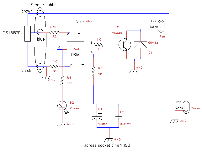
This is a fan controller designed for an audio/video cabinet. It utilizes a PICAXE 08M microcontroller and a DS18B20 temperature sensor. The fan activates at 30 degrees Celsius (approximately 86 degrees Fahrenheit) and deactivates at 28 degrees Celsius (around...
It was one of those days when learning chemistry, philosophy, and literature seemed necessary. Contemplating my plans for the day, I decided to embark on a project that I had wanted to undertake for a long time but had...
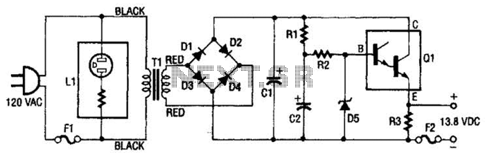
This regulated power supply consists of a step-down transformer T1, a full-wave rectifier bridge (D1 through D4), and a filtering regulator circuit made up of C1, C2, R1, R2, R8, D5, and Q1. When 120 Vac is provided, the...