
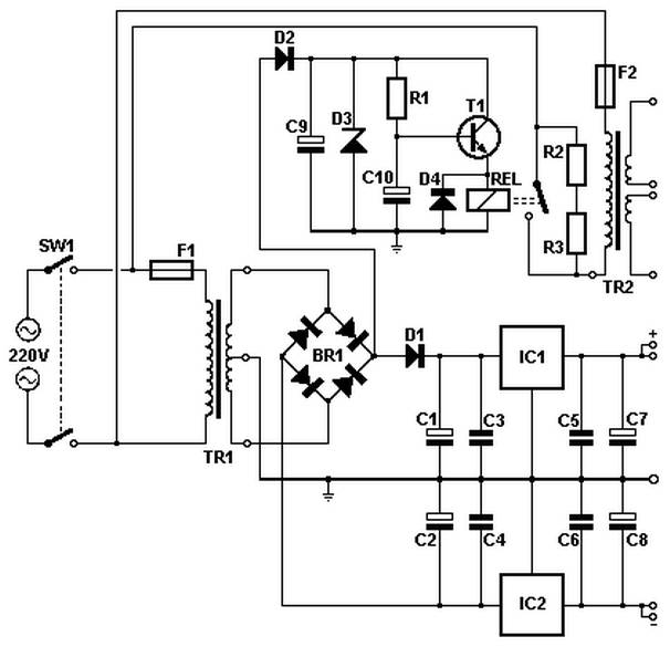
Simple regulated power supply with overcurrent trip
The circuit utilizes a 15V zener diode for voltage regulation, ensuring a stable output voltage. The input voltage is connected through a 4.7k ohm resistor, which limits the current flowing into the zener diode. The zener diode clamps the voltage at 15V, and with a forward voltage drop of 0.6V across the base-emitter junction of the PNP transistor, this results in a voltage of 14.4V across the 3.3k ohm resistor. The calculated current through this resistor is approximately 4.4mA, which is significant for the operation of the circuit.
The PNP transistor acts as a current amplifier, allowing the small base current to control a larger emitter current. The emitter of the PNP transistor is connected to the input of a BFR39 transistor and a 2N6254 transistor, which are configured to switch on when sufficient current flows from the emitter. The presence of diode D1 in the circuit is crucial, as it prevents any backflow of current that could potentially disrupt the operation of the PNP transistor.
In scenarios where there is no load connected to the output, the current flowing through the PNP transistor can still trigger the BFR39 and the 2N6254 transistors, ensuring that they remain in an active state. This design allows for efficient current management within the circuit, maintaining performance even under varying load conditions. The overall configuration supports reliable operation for applications that require regulated voltage and current amplification.The 15v zener is fed via the 4K7 resistor from the input. With 0.6v across the base - emitter of the PNP transistor, this establishes a voltage of 14.4 across the 3K3, so there must be a current of nearly 4.4mA through the 3K3. This current is available to feed the emitter of the transistor - provided that the diode D1 doesn`t pinch any of it.
However with no load on the output, some of this current flows through the PNP to turn on the BFR39 and the 2N6254 which will conduct. 🔗 External reference
Related Circuits
Soft power for a large transformer is implemented by using a series resistance of 100 ohms at 10 watts, or alternatively, two resistors of 47 ohms at 5 watts each in the primary circuit. The resistance is bypassed by...
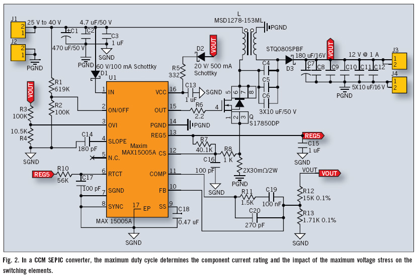
The Single-Ended Primary Inductance Converter (SEPIC) topology is an effective solution for automotive power systems that necessitate an output voltage that falls between the low and high values of the input voltage. The SEPIC topology is suitable for this...
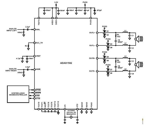
This is a stereo circuit schematic of the ADAU1592, a 2-channel, bridge-tied load (BTL) switching audio power amplifier. The ADAU1592 can be utilized in compact television sets, PC audio systems, and mini-component applications. According to the ADAU1592 datasheet, an...
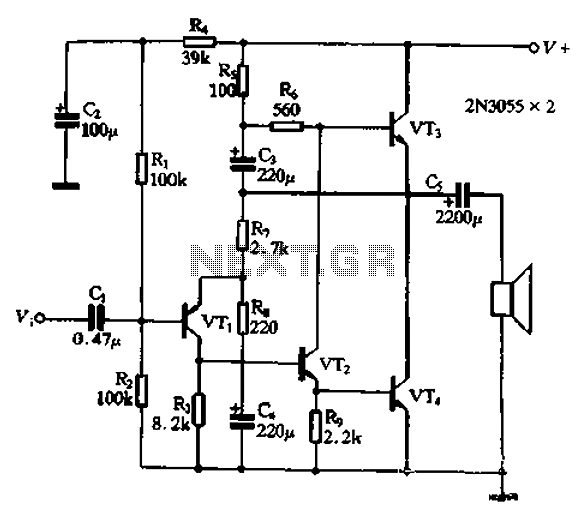
The circuit illustrated in Figure 240 is straightforward, utilizing only four transistors to process the input voltage, resulting in a large, inverted output. This configuration serves as a high-performance amplifier, delivering excellent high-fidelity power discharge capabilities. The input stage...
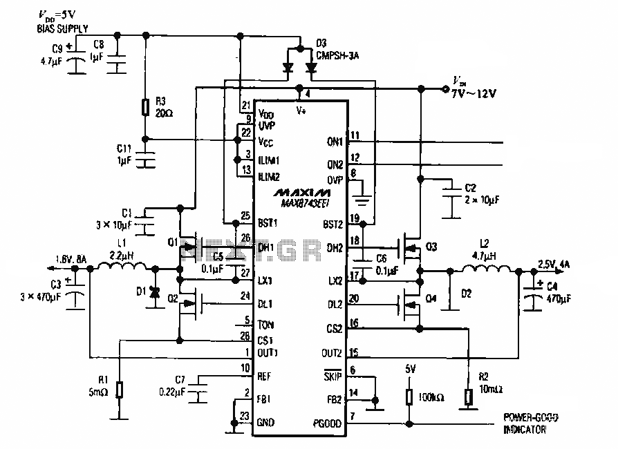
The circuit utilizes the MAX8743 chip for a laptop chipset power supply. It demonstrates the conversion of a 5V power supply into +2.5V and +1.8V outputs. The MAX8743 is a highly integrated power management solution designed specifically for laptop chipsets....
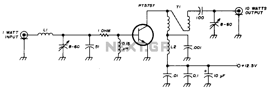
This 10-watt, 144-MHz power amplifier utilizes a TRW PT5757 transistor. The inductor LI consists of 4 turns of no. 20 enameled wire with a 3/32" inner diameter, while inductor L2 comprises 10 turns of no. 20 enameled wire with...