
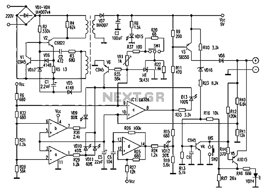
Accelerometer Schematic

The schematic represents a printed circuit board (PCB) designed for an accelerometer application utilizing an Atmel AT89S8252 microcontroller. This microcontroller is a variant of the 8051 architecture, which offers in-circuit programming capabilities via a Serial Peripheral Interface (SPI). The SPI interface is crucial for both programming the microcontroller and interfacing with a MultiMediaCard (MMC), which serves as a data storage medium.
To facilitate the dual functionality of the SPI pins, the design incorporates a jumper block positioned below the 74AHC244 buffer/driver chip. This jumper block is labeled "P" for programming mode and "R" for run mode, allowing the user to select the appropriate configuration based on the operational requirements. It is important to note that the 74AHC244 must be from the 74AHC family, as other variants such as 74LS or 74HC may not be compatible for long-term operation due to differences in electrical characteristics.
The accelerometer is represented in the schematic as a surface mount device (SMD), which indicates that it is mounted directly onto the PCB. This configuration allows for a compact design and efficient use of space. The schematic also depicts the MMC socket, which is similarly shown from the bottom perspective, illustrating its placement on the PCB as viewed through the board.
Additionally, the accelerometer features an external resistor that is utilized to select the data rate, providing flexibility in the operational parameters of the device. This resistor is critical for optimizing performance based on the specific application requirements, ensuring that the accelerometer can operate effectively across various conditions. Overall, the schematic provides a comprehensive overview of the layout and functionality of the accelerometer PC board, emphasizing the critical components and their interconnections.Below is a rough schematic of the layout of the accelerometer PC board looking from the component side. The microcontroller is an Atmel AT89S8252, an 8051 clone. This microcontroller is in-circuit programmable using an SPI interface. The SPI pins are also used to drive the MMC. To permit the dual use there is a jumper block (located below the 74AHC244, marked "P" and "R") that allows the pins to be connected for programming (P) or running the code (R).
Speaking of the 74AHC244 chip, it MUST be the 74AHC family version. Regular old 74LS or 74HC etc. will not work, at least not for long. The accelerometer itself is a surface mount chip and is thus shown from the bottom on this schematic as if you were looking through the board. The same holds true for the MMC socket. The accelerometer has an external resistor used to select the data rate 🔗 External reference
Related Circuits
Chaolitong Phone Travel Charger for Motorola models 308, 328, 338, and 368 series mobile phone batteries. This charger features a switch for nickel-cadmium, nickel-hydrogen, and lithium-ion batteries, along with a discharge function. It operates with an AC mains input...
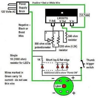
A DIY espionage kit is not complete without a long-distance listening device, particularly one that incorporates a laser. This project demonstrates how to utilize a laser pointer to capture sounds from hundreds of feet away. The materials required include...
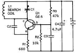
This metal detector circuit needs to be powered using a 9 volts power supply (DC) or a 9 volts battery. The C1 capacitor is a variable capacitor with a value of 365 pF, C2 is a 100 pF silver...
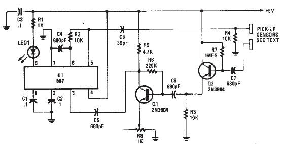
A simple proximity detector electronic project can be designed using this schematic circuit. This project utilizes a tone decoder integrated circuit (NE567), which provides a signal with a frequency of approximately 100 kHz. When an object is placed near...
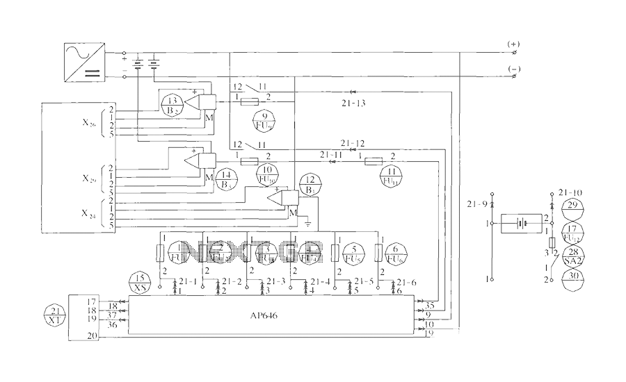
The components include B2 (13) and B3 (14) designated for the Hall current sensor; FU9 (9) and FU10 (10) serve as fuses; an AP646 alarm signal is connected to the fuse board; terminals X24, X26, and X29 function as...
Boss MT2 Metal Zone Distortion Pedal Schematic. The MT-2 Metal pedal is one of the most popular guitar pedals, providing over-the-top, insane distortion tones with huge mids and lows and an ultra-saturated sound. The Boss MT-2 Metal Zone Distortion Pedal...