
Adding an Inrush Current Reducer to an Astron Linear Power Supply
The implementation of an inrush current limiting device is critical for the longevity and reliability of high-power linear power supplies. The surge current that occurs when the power supply is turned on can create stress on the transformer and associated components, potentially leading to premature failure. The use of a thermistor provides a passive solution that requires no active components, thus simplifying the design and reducing potential points of failure.
The thermistor's placement in the circuit is crucial. It must be positioned between the fuse and the power switch to ensure that it can effectively limit the inrush current before it reaches the transformer. The initial high resistance of the thermistor limits the current during startup, and as it heats up, its resistance drops, allowing normal operation. This characteristic is particularly beneficial in applications where frequent power cycling occurs, providing a reliable means of protecting the power supply.
When selecting a thermistor, it is essential to consider the current rating of the power supply to ensure that the device can handle the maximum expected inrush current. The chosen thermistor, with a resistance of 2.5 ohms and a current rating of 11 amps, is suitable for many high-power applications. The installation process involves careful soldering to avoid damage to the power supply's internal components and ensuring that all connections are secure.
For the wiring modifications, it is advisable to document the original configuration, especially if the power supply's design varies from the provided schematic. This documentation will facilitate troubleshooting and future modifications. Terminal strips provide a convenient way to make connections, allowing for easy replacement or adjustment of components without soldering directly to the circuit board.
In summary, modifying an Astron linear power supply to include an inrush current limiting thermistor enhances its performance and reliability. This modification not only protects the internal components from excessive stress but also contributes to the overall stability of the power supply during operation. Proper installation and selection of the thermistor are key to achieving the desired results.Those of you who own large 500 watt and higher Astron linear power supplies, and even large HF amplifiers, know all too well that "GNNNNnng" sound that they often make when turned on. This is due to the high inrush (surge) current flowing into the transformer when the filter capacitor is discharged.
Depending on the size of the supply, this surg e can exceed the rating of the circuit breaker on the outlet the supply is plugged into, but as it`s so brief, the fuse on the back of the supply rarely blows during these surges. There are several ways to prevent this: Leave the supply on all the time. Even if it`s left on all the time, there will still be momentary power outages and interruptions, so this really isn`t a true solution.
Purchase a commercial inrush current limiting device for about $80US. Here`s one that plugs into the wall, has its own on/off switch, and provides an inrush current limited outlet for any load. Unfortunately you must use the power switch in the external box and leave the supply`s conveniently located power switch turned on all the time.
You can make a similar device yourself with a relay and a resistor and you can install it between the power switch and the transformer inside your unit. Add a thermistor in series with the input of the supply. This is a small negative temperature coefficient device that gets wired in series with the transformer.
It has a high initial resistance (high compared to the resistance the transformer presents when power is first applied) but as current is drawn and the device gets hot, the resistance decreases (hence the negative temperature coefficient). It regulates itself, providing a current limiting resistance when cold and almost no resistance when hot.
It does this with no moving parts, unlike units that use a relay. It can be installed inside or outside the power supply and doesn`t require any other components. All switching power supplies have a thermistor in series with either the incoming AC line or the output of the bridge rectifier before the filter capacitors. This site has a lot of good information about thermistors, when to use them, how to select them, etc.
I opted for choice #3 above. I purchased some 2. 5 ohm 11 amp devices from Mouser, part number 871-B57364S259M, for about $2US each. I had also purchased some five-lug terminal strips for another project, Mouser part number 158-1005, for about $1US each, and used one of these in my Astron RS-35M power supply. A few inches of #16 stranded hookup wire completed the job. I modified an older supply, one that has the line cord permanently attached. You may have to alter the procedure a bit if yours is newer and has the IEC input connector. You may also have to choose a slightly different thermistor depending on the current rating of your power supply.
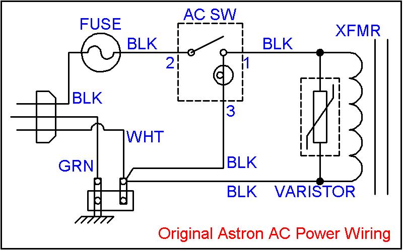
The original Astron linear power supply primary (AC input) wiring is shown in the diagram below. The thermistor should be installed between the fuse and the power switch. Compare your AC wiring to the diagram above and make notes or a drawing if it differs significantly. The terminals on the switch are actually numbered along the side, from 1 to 3, bottom to top. Unsolder the green and white AC power cord wires going to the small two-lug terminal strip near the AC input. If your supply has the IEC input connector, you may have to unsolder the wires coming from it. Remove the remaining wires from the terminal strip. On my supply, one went to the top terminal (3) of the front panel power switch (to light the internal lamp) while the other went to the transformer.
I`ll identify the lugs and holes of the terminal strip by numbers: 1 through 5, going from left to right, with the mounting hole facing away from you. The lugs stick up above the phenolic strip; the holes are in the middle of the phenolic strip. The terminal strip will be mounted in the existing hole in the chassis with lug 1 toward the rear of t
🔗 External reference
Related Circuits
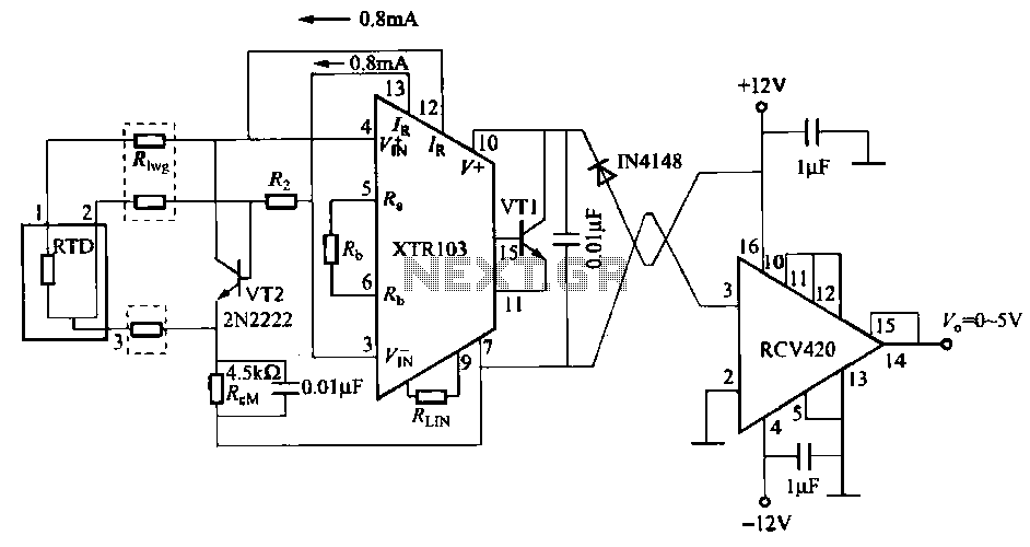
When the RTD temperature sensor is positioned far from the amplifier, the resistance of the sensor leads and their susceptibility to interference and other issues cannot be overlooked. The circuit shown in the figure addresses this problem. It utilizes...
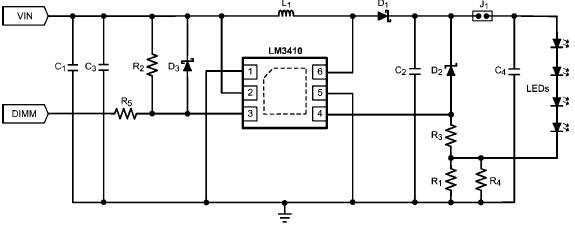
The LM3410 constant current LED driver is a monolithic integrated circuit that enables the design of high-efficiency, low-cost lighting solutions using a minimal number of electronic components. It employs current-mode control and internal compensation to ensure optimal performance across...
The success or failure of lighting upgrades depends on the quality of components and workmanship. Proper wire routing is essential to prevent insulation chafing. The quality of soldering connections is crucial, as poor solder joints can corrode and fail....
Iron the printed layout at a low heat setting until the ink adheres to the PCB. This process may take over an hour to complete. Afterward, remove the transparent paper. Next, submerge the PCB in Ferric Chloride solution until...
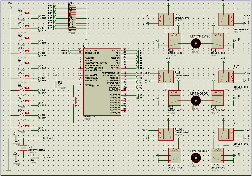
The NE555 circuit implementation involves various connections and configurations. The circuit is designed with a supply voltage (Vcc) of +11V. The input terminal (pin 3) serves as a reset pin, and the relay and motor components are integrated into...
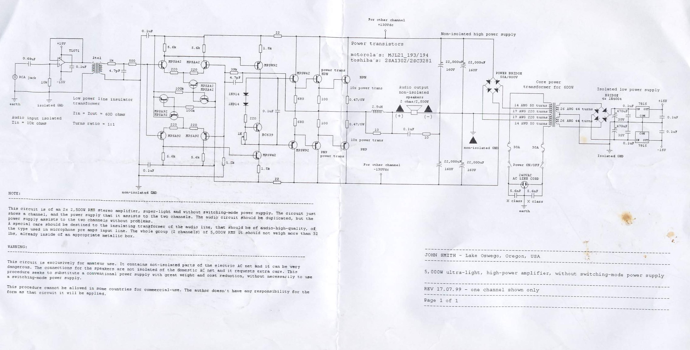
This circuit is for a 2x2, 500W RMS stereo amplifier that is super-light and does not utilize a switching-mode power supply. The circuit diagram displays only one channel, while the power supply is designed to support both channels. The...