
Allarm circuit
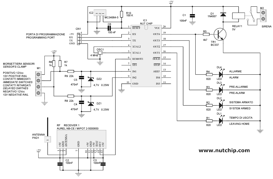
To facilitate understanding, the main schematic can be viewed as a series of blocks: radio front end, contact inputs, reset generator, outputs, power supply, and the core logic provided by the Nutchip. A wireless alarm sensor functions similarly to a remote control. Upon detection of movement within its range, the sensor transmits a pulse train, akin to pressing a remote control button. This pulse train is received by a radio receiver module on the main board, which relays the signal to the Nutchip's remote control pin. The Nutchip decodes the signal, distinguishing between immediate and delayed sensors, in addition to true remote control signals for circuit activation and deactivation.
It is important to note that in radio-based designs, a quality radio receiver cannot substitute for a good antenna. The circuit performs adequately with a homemade antenna (a straight insulated wire), unless budget allows for a superior option. In addition to wireless sensors, the schematic accommodates wired sensors, which are treated as normally closed contacts that break upon detection of movement or when doors and windows are opened. These sensors often include a secondary anti-tamper contact that disconnects if the device casing is opened or tampered with. Therefore, two inputs are necessary: one for anti-tamper and immediate contacts and another for delayed contacts. The immediate input connects to the Nutchip pin IN1, while the delayed input connects to pin IN2.
Due to the potential for noise and interference in long wiring runs, two identical networks are implemented to clean and clip the input signal before it reaches the chip. These networks consist of components R7-R9-C5-DZ2 and R6-R8-C4-DZ1, respectively. All outputs are linked to LED diodes (DL1, DL2, DL3, DL4) to indicate the status of the main board. The fourth output is connected to a siren via RELAY1. Given that this circuit is designed for continuous operation, it must account for brown-outs, which are significant drops in mains voltage that do not result in a complete shutdown. Brown-outs can be detrimental to electronic devices, leading to improper or incomplete resets with unpredictable outcomes. To mitigate this risk, IC2, a specialized voltage detector and reset generator, has been integrated. Along with the delay network formed by R10-C6, it ensures a smooth reset of the circuit even under adverse conditions.
The board requires a 12V DC power supply, and it is common practice to power alarm systems using a battery that is kept in a constant state of recharge, ensuring resilience against power outages. Most alarm sensors also necessitate a 12V DC power supply. The battery must be sufficiently sized to support both the central unit and the sensors for a designated duration. To generate a stabilized 5V power supply for the Nutchip, a traditional regulator based on the 7805 (IC3) is employed, as illustrated in the schematic. To activate the alarm system, the first push button on the remote control (key1) must be pressed, causing LED DL1 to illuminate, thereby signaling that the system is operational.Making yourself an alarm is both useful and interesting: but the best part is when you take the remote control out of your pocket, and switch on the alarm while saying to your friends: "I`ve done it in a weekend". Making yourself an alarm gives you maximum flexibility: as this project works according to the Nutchip truth table, you can change it to suit your needs.
Some people would like to have like a "panic" button, in order to sound the siren. Some other pepople need a very long time to leave the house. Or you might be looking for an alarm that keeps that special sensor on even if you are at home. Possibilites are unlimited! All of these sensors can be configured for either immediate or delayed alarm. Delayed alarms are required to allow some time for the legitimate user to get in an switch the alarm off. Let`s approach the main schematic as if it was made of blocks in order to understand it more easily. These blocks are: radio front end, contact inputs, reset generator, outputs, power supply and, of course, core logic provided by the Nutchip.
A wireless alarm sensor is similar to a remote control. When someone enters its detection range, a wireless sensor sends an impulse train as if someone pressed a special remote control key. A radio receiver module on the main board detects the pulse train, and forwards it to Nutchip` REMOTE control pin.
The Nutchip decodes the signal, differentiating between immediate and delayed sensors (aside from true remote control signals used for switching the circuit on and off). As for all radio-based designs, always remember that a good radio receiver cannot replace a good antenna.
The circuit works well with an home made antenna (straight insulated wire), unless if your budget has enough room for a better one. Wireless sensors aside, our schematic provides also inputs for wired sensors. Such sensors are treated as normally closed contacts, that break when someone enters their range or opens a door or window.
It is often the case that they provide a second anti-tamper contact, that breaks if you open the case or attempt a sabotage. Therefore we need two inputs: one for connecting anti tamper and immediate contacts and another one for connecting the delayed contacts.
The "immediate" input is connected to the Nutchip pin IN1, and the "delayed" on to pin IN2. As the wires are usually long enough to collect any sort of noise and interference, a couple of identical networks provide quite an energic cleanup and clipping on the input signal before it arrives to the chip. These networks are built around R7-R9-C5-DZ2 and R6-R8-C4-DZ1 respectively. All of the output are connected to a LED diode (DL1, DL2, DL3, DL4), in order to display the status of the main board.
A siren is connected to the fourth output, through RELAY1. As this circuit is designed for uninterrupted service, brown-outs are a possibility that cannot be excluded. A brown-ut is a big decrease in the mains voltage level that does not end into a black out. Brown-outs are dangerous for electronics devices, because it can result in improper or partial reset with impredictable consequences.
This is why whe have added IC2, a special voltage detector and RESET generator. Together with the delay network R10-C6, it ensures a graceful reset to the circuit even in worst cases. The board requires a 12Vdc power supply. It is common practice to power an alarm from a battery (kept under constant recharging), in order to be immune from power shortages.
Most alarm sensors require a 12Vdc power supply as well. The battery must be big enough to power the central AND the sensors for an appropriate period of time. To create a stabilized 5 volt power source required by the Nutchip, we adopted a "classic" regulator, based on the 7805 (IC3), as shown in the schematic on the left.
To engage the alarm system press the first pushbutto on the remote control (key1). LED DL1 will lights up: starting now 🔗 External reference
Related Circuits
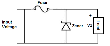
An overvoltage protection circuit is designed to safeguard electronic components from excessive voltage that could potentially cause damage or destruction. This project involves constructing a straightforward yet effective overvoltage protection circuit using a fuse and a zener diode as...

The following circuit illustrates a practical electronics astable circuit diagram based on the 555 Timer IC. This circuit produces a pulse frequency of approximately 2Hz with a very low mark-space ratio, making it suitable for various applications. The single...
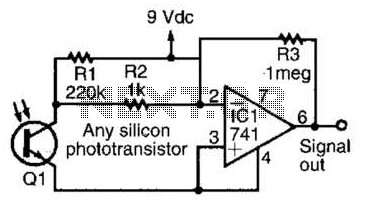
This simple amplifier is compatible with nearly any phototransistor. Although the 741 operational amplifier is designed for use with a split supply, it can also function effectively with a single-sided supply. The described amplifier circuit utilizes the 741 operational amplifier...

This simple circuit indicates the status of a phone, including Line OK, Dialing, and Call Attended. It also features a locking mechanism to block outgoing calls while allowing incoming calls, preventing misuse of the telephone. The circuit requires only...
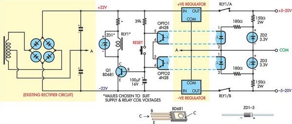
This circuit was designed to protect a dual rail power supply from shorts across the two rails. It uses an optocoupler to monitor each supply rail, with the internal LEDs powered from ZD2 and ZD3 and the associated resistors....
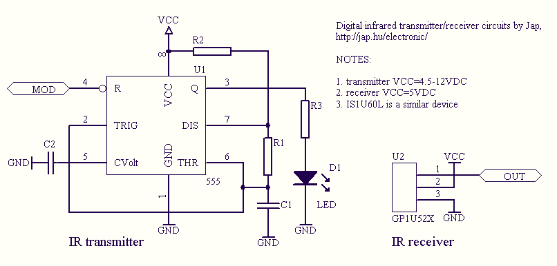
Infrared remote controls are using a 32-56 kHz modulated square wave for communication. These circuits are used to transmit a 1-4 kHz digital signal (OOK modulation) through infra light (this is the maximum attainable speed, 1000-4000 bits per sec)....
Warning: include(partials/cookie-banner.php): Failed to open stream: Permission denied in /var/www/html/nextgr/view-circuit.php on line 713
Warning: include(): Failed opening 'partials/cookie-banner.php' for inclusion (include_path='.:/usr/share/php') in /var/www/html/nextgr/view-circuit.php on line 713