
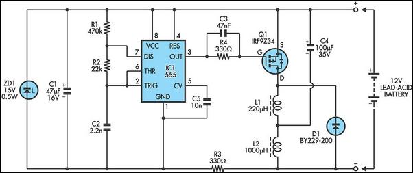
Overvoltage Protection Circuit

To limit the circuit to a specific voltage, a zener diode with the corresponding breakdown voltage rating should be selected. For example, to limit the circuit to 5V, a zener diode rated at 5V should be used. Once the voltage surpasses this threshold, the zener diode will conduct and divert excess current to ground, preventing the load in parallel from receiving that excess voltage. The fuse in this circuit provides additional protection by blowing if the current exceeds a specified limit, which is determined by the fuse's current rating. Fuses are available in various ratings; for instance, a 0.5A fuse will blow if the current exceeds 500mA. Thus, the fuse protects against excessive current, while the zener diode protects against excessive voltage. The input voltage source can be any DC power source, such as batteries or a DC power supply. Jumper wires will be necessary to connect the electronic components. The voltage rating of the zener diode should be chosen based on the desired voltage for the load, while the current rating of the fuse should be selected based on the maximum current limit for the circuit. Since the voltage in parallel is uniform across all components, the voltage across the zener diode will also be the voltage received by the load. Selecting a zener with a breakdown voltage of 5V ensures that the load will receive 5V until that threshold is exceeded, at which point the zener diode will conduct, preventing excess voltage from reaching the load.
The overvoltage protection circuit can be constructed using the following components: a zener diode with an appropriate breakdown voltage, a fuse rated for the desired current limit, and a DC voltage source. The circuit can be arranged by connecting the zener diode in parallel with the load, ensuring that the cathode is connected to the positive side of the voltage source while the anode is connected to the ground. The fuse should be placed in series with the load to monitor the current flowing through the circuit. When the input voltage exceeds the zener diode's breakdown voltage, the diode will conduct, effectively clamping the voltage across the load to the zener voltage. If the current flowing through the circuit exceeds the rating of the fuse, the fuse will blow, disconnecting the circuit from the power source and providing a secondary layer of protection. This arrangement ensures that both overvoltage and overcurrent conditions are mitigated, safeguarding sensitive electronic components from potential damage. Proper selection of the zener diode and fuse ratings is critical for the effective operation of the circuit, allowing for tailored protection based on specific application requirements.An overvoltage protection circuit is a circuit which protects electronics from excess voltage, which could potentially damage or destroy electronic components. In this project, we will build a simple, yet effective, overvoltage protection circuit using a fuse and a zener diode, as the protecting elements, that will work for electronics that operat
e with DC voltage. The zener diode that you will choose depends on how much voltage you want to limit the circuit to. Zener diodes are rated with all differing amounts of breakdown voltage ratings. The breakdown voltage is the amount of reverse voltage which a zener diode can receive before it breaks down and begins conducting reverse current across its junctions. A zener diode will not conduct current across its terminals unless this threshold breakdown voltage is reached.
Before the threshold voltage is reached, zener diodes will simply "hold" the voltage across its terminals that is exposed to. For example, if a zener diode is rated for a breakdown voltage of 12V and it is exposed to a voltage of 3V, it will simply hold the 3V across its terminals and not conduct any current across its terminals.
If the voltage reaches above 12V, then the zener diode will break down and conduct current across its terminals. Therefore, use the zener diode with a voltage rating that you want to limit your circuit to. If you want to limit your circuit to 5V, then use a zener diode with a breakdown voltage rating of 5V.
After this 5V threshold is reached, the zener diode will conduct current across its terminals and shunt excess power to ground. If you want to limit your circuit to 12V, then choose a zener diode with a breakdown voltage rating of 12V.
After this threshold is reached, the diode will break down and shunt all excess power to ground. While "broken open", the zener diode will no longer hold voltage across its terminals, so the load in parallel with the zener will not receive this excess voltage. The fuse in this circuit really serves to be an additional protection to the zener. If the voltage is exceeded and, thus, the zener breaks down and conducts current, the fuse will break open if the current exceeds a certain amount, which is determined by the current rating of the fuse.
The fuse that you will need is the amount of current you want to limit your circuit to. There are all types of fuses available to limit differing amounts of currents. Some fuses limit current to 1 amp. Others 2 amperes. Others 3 amperes. Whatever current you want to limit the circuit to is the fuse that you will choose. For example, if you want no more than 500mA of current to flow through your circuit, you will choose a 0. 5amp fuse. This fuse will blow when this threshold is reached. Therefore, it serves to protect the circuit against excess current, while the diode serves to protect the circuit for excess voltage.
The input voltage source can be from any power source such as batteries or a DC power supply. And you`ll need a few jumper wires to connect all electronics components together. Again, you choose the voltage rating of the zener based on the voltage you want the load to be limited to. And you choose the current rating for the fuse based on what current you don`t want the circuit to be exposed to.
Since voltage in parallel is equal across all components in a circuit, the voltage that falls across the zener diode will fall across the load in parallel with the zener diode. So by choosing the voltage rating of the zener carefully, we decide the voltage that the load will receive.
If we choose a zener with a breakdown voltage rating of 5V, then the load will received 5V when the zener receives 5V. After this amount, the zener will break down and conduct current to ground. Since its resistance has broken down and it is now conducting, its voltage drops dramatically, so the load in parallel does not receive this excess voltage.
🔗 External reference
Related Circuits
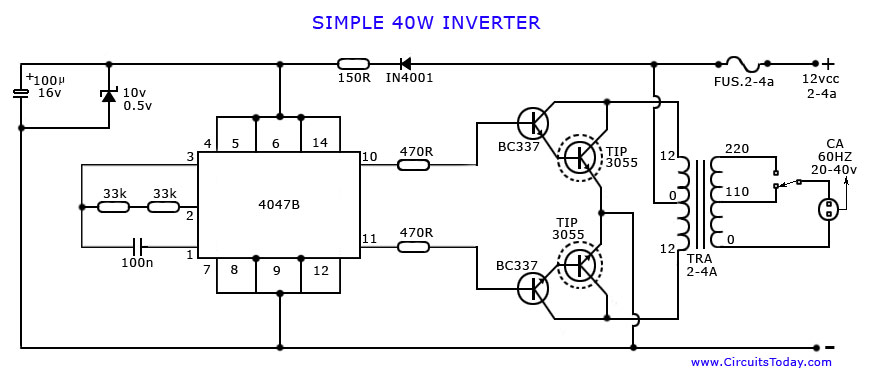
An article on how to create an inverter using a simple 40-watt inverter circuit diagram and schematics. This inverter converts 12 volts to 220 volts using the CD4047 integrated circuit. The described inverter circuit utilizes the CD4047 IC, which is...
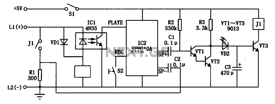
An automatic telephone responder circuit is illustrated. It incorporates a 10-second voice recording circuit (SR9G10A) activated by the power switch (S2). The circuit utilizes an electret microphone (IC2) for sound input. To initiate the response, the user must press...
The circuit is designed for high precision operation over an extended temperature range, provided that V+ remains relatively constant, as the current IZ is dependent on V+. Resistors R1, R2, R3, and R4 are selected to ensure the appropriate...
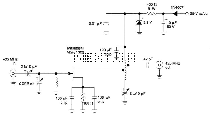
This circuit is a low-noise preamplifier designed for the 435-MHz amateur satellite frequencies. It utilizes a Mitsubishi MGF1302 transistor. A 28-Vdc power source is indicated; however, lower voltages can be employed by adjusting the 400-5-W resistor. The low-noise preamplifier circuit...
The metal detector circuit includes a fixed frequency oscillator, mixer, detector, detection oscillator, and power amplifier circuit. The fixed frequency oscillator circuit is composed of a ceramic filter (ZC), transistor (V1), resistors (R1 to R4), capacitor (C2), and other...
The following circuit illustrates a 6/12/24V Lead Acid Battery Charger Circuit Diagram. Features: It is essentially a high-voltage pulse generator. The circuit diagram for a 6/12/24V Lead Acid Battery Charger is designed to efficiently charge lead-acid batteries of varying voltages....