
AM band Transmitter
The described radio transmitter circuit is an effective solution for hobbyists and experimenters looking to engage in AM broadcasting within legal micro-power limits. The design emphasizes stability and fidelity, making it suitable for various audio sources, including mixers and CD players. The careful selection of components, particularly in tuning the output tank to the crystal frequency, is crucial for achieving optimal performance. The use of a variable inductor or capacitor allows for fine-tuning, which is essential in ensuring maximum output efficiency and signal clarity.
In practical applications, the transmitter's performance can be monitored using a simple output meter, which aids in adjusting the antenna for the best possible reception. The design accounts for the challenges posed by short antennas, incorporating a loading coil to enhance radiated power and compensate for the low radiation resistance. The ability to make adjustments based on antenna length and frequency ensures versatility in various broadcasting scenarios.
The choice of crystal frequency plays a significant role in the transmitter's effectiveness, with recommendations to avoid frequencies near strong local stations. This consideration is vital for reducing interference and maximizing the transmitter's range. The modulation capabilities of the transmitter further enhance its functionality, allowing for clear audio transmission. Overall, this radio transmitter circuit presents a well-rounded approach for those interested in exploring AM broadcasting with a focus on quality and reliability.The picture to the left is a high quality radio transmitter for the A. M. broadcast band. The transmitter legally operates with "micro-power" and will not set any distance records but, unlike simpler designs, the frequency stays put and the fidelity is excellent. Although the schematic looks somewhat complex, the circuitry is easy to build and adju st for experimenters with a little "tweaking" experience. A simple output meter confirms proper signal level and checks antenna tuning while "on the air". Add an audio mixer, tape recorder, and perhaps a CD player and have a near-professional micro-power station. Most values are not critical but a few choices must be made carefully for best results. The output tank is tuned to the crystal frequency by selecting the values from the chart above. For example, for a 1 MHz transmitter, the chart indicates 500 pf and 35 uh. A 33uH and 550pF (470 + 82, perhaps) would be a good start. This chart assumes that a 220 pf capacitor is already connected between the collector and base of the output transistor as indicated in the schematic so the indicated capacitance is in addition to the 220 pf.
A variable inductor or capacitor will allow the tank to be fine-tuned for the maximum meter reading with no antenna connected (a few volts with a 10 megohm voltmeter or about 50 microamps with a current meter). After the antenna is connected, the loading inductor in series with the antenna is selected for the minimum meter reading (best antenna loading).
(A 3 foot antenna will need about 820 uH for a 1. 6 MHz output frequency. ) Longer antennas or higher frequencies need less inductance and shorter antennas or lower frequencies will need more. The meter reading should drop by more than half with a reasonably good antenna but the reading can be ignored if sufficient transmit range is achieved.
The antenna, which is short relative to the wavelength, is hard to match well because it has a very low radiation resistance in series with a very small capacitor. (The power dissipated in the radiation resistance is the power that is transmitted. ) The loading coil helps to resonate out some of the series capacity resulting in more antenna current and thus more radiated power.
Some retuning of the tank may be desirable when the loading coil value is changed. A remote radio playing back through a baby monitor or walkie-talkie makes a good signal quality monitor for antenna tuning and positioning. Note: The antenna in the picture above is just a short metal rod from an old fireplace screen stuck through an important-looking insulator strictly for appearance.
It`s really too short for optimum range. The 470 ohm resistor across the tank controls the Q when the antenna is short. You might be able to increase or even eliminate that resistor if your antenna and ground system are good enough. Try increasing the value, listening for distortion in a nearby radio. The crystal can be practically any surplus crystal with a fundamental frequency between 530 kHz and 1.
7 MHz in 10 kHz increments but the higher frequencies work best. Choose a crystal frequency away from strong local stations at or above 800 kHz for best transmit range. Proper operation of the oscillator may be verified by probing the junction of the two 1000 pf capacitors with a high impedance oscilloscope probe connected to a scope or frequency counter.
Full modulation is achieved by applying about 2 volts peak-to-peak to the base of the current source transistor in the differential amplifier. The modulation voltage varies the current in the diff. amp. away from the nominal 20 ma. setpoint and this modulated current is converted to a clean, high voltage sinewave by the output tuning circuit.
The modulated signal may be observed with an oscilloscope connected to the antenna terminal if desired. The photo above shows a prototype built with metal transistors (just for looks!) and with a few additions like
🔗 External reference
Related Circuits
The Software Defined Radio (SDR) hardware, in its most basic configuration, includes a wideband switched balanced mixer and a low noise LF amplifier. This straightforward hardware demonstrates remarkable sensitivity and linearity, making it suitable for both testing and regular...
The MAR6 (MSA-0686, 0685, 0885) is a high-performance silicon bipolar Monolithic Microwave Integrated Circuit (MMIC) housed in a cost-effective surface-mount plastic package. This MMIC is designed to function as a general-purpose 50 W gain block. Its applications encompass both...
The operation of the 6CL6 transmitter is quite sophisticated despite the simple appearance of the circuit. The core of the circuit is the electron-coupled crystal oscillator. This circuit integrates the functions of an oscillator and amplifier into a single...
This circuit is a simple two-transistor (2N2222) mini FM transmitter. No authorization is required for this transmitter according to FCC regulations regarding wireless microphones. When powered by a 9-volt battery and equipped with an antenna no longer than 12...
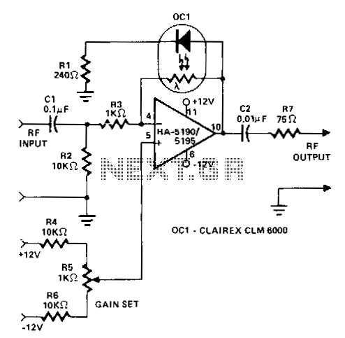
This circuit operates as a wideband adjustable automatic gain control (AGC) amplifier. It has an effective bandwidth of approximately 10 MHz and can handle RF input signal frequencies ranging from 3.2 to 10 MHz at levels between 40 mV...
The circuit utilizes two 2N3819 FETs arranged in a cascode configuration. The lower FET functions in common source mode, while the upper FET operates in common gate mode, achieving full high-frequency gain. The lower FET is tunable, enabling peak...