
Amplifier Schematic
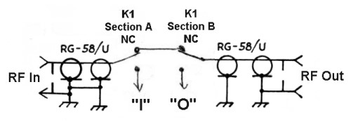
In a grid-driven amplifier, the impedance matching between the transmitter and the tube is critical for efficient performance. The input link, which comprises L1 and L2, serves as a transformer to elevate the voltage from the transmitter, enabling effective signal transfer. The use of RG-58 coaxial cable ensures minimal signal loss during transmission from the input jack to the amplifier's input.
The grid tuning capacitor C1 plays a significant role in achieving resonance, which is essential for optimal amplifier operation. The grid bias, introduced through a resistor, ensures that the tube operates within its linear range during SSB operation. The careful design of the resistor values and the use of a parasitic suppressor enhance stability and prevent oscillations that could lead to distortion or damage.
The RF choke and coupling capacitors are strategically placed to manage the DC and RF components separately, ensuring that the amplifier can deliver the desired RF output while maintaining safety standards. The pi-network configuration in the output stage is crucial for filtering harmonics and ensuring a clean signal is transmitted to the antenna.
Furthermore, the metering setup is designed for effective monitoring of the amplifier's performance, allowing for adjustments and troubleshooting as needed. The choice between individual and shared meters reflects a balance between functionality and practical constraints in terms of space and cost. Overall, the design principles applied in this grid-driven amplifier highlight the intricate balance between electrical performance, safety, and usability in RF amplification systems.In a grid driven amplifier it is necessary to match the low impedance of the driving transmitter (typically 50 ohms) to the high impedance input of the tube (typically several thousand to several million ohms). The signal from the input jack travels via RG-58 coaxial cable through relay K1 to the input link L1, which consists of three turns of insulated hookup wire on coil L2.
L2 is tuned to resonance by the grid tuning capacitor C1. The transformer action of L1 and L2 steps up the voltage, matching the low impedance of the driving transmitter to the high impedance input of the tube. If extra driving power is available, as is the case with the 6CL6 transmitter, the grid tuning control is used as a drive level control, and is tuned off resonance to reduce the drive to an acceptable level.
Grid bias is fed into the bottom of L2 and travels through the 15 ohm resistor to the grid of the tube. When operated as a linear amplifier (SSB), the tube does not draw grid current and the 15 ohm resistor has no effect.
However, if the tube is driven hard enough for grid current to flow (CW operation), the 15 ohm resistor introduces additional grid bias and the tube operates as a non-linear class C amplifier. In an RF amplifier it is necessary to supply DC plate voltage to the tube (about 600 volts in this case) and at the same time extract the amplified RF that appears at the plate of the tube.
In the circuit at right, the 1 mH plate RF choke allows the direct current from the plate supply (B+) to pass through it, while preventing the RF on the plate of the tube from flowing back through the plate supply. At the same time, the 1000 uuf plate coupling capacitor (at the top in the schematic) permits the RF on the plate to flow though to the output tank circuit while blocking the plate voltage.
The 0. 01 uf capacitor at bottom short circuits any residual RF that might have gotten through the plate choke and prevents it from reaching the plate supply. The 100 ohm resistor and small coil (RFC2) in series with the plate lead form a parasitic suppressor, which helps prevent unwanted oscillations.
The plate tank circuit is a pi-network that matches the high impedance of the plate to the low impedance of the antenna. At the same time the circuit filters out undesired harmonics from the output signal. The signal from the plate enters through the 1000 uuf plate coupling capacitor at the upper left in the schematic.
The 300 uuf plate tuning capacitor in combination with the plate tank coils L3 and L4 tunes the amplifier to resonance. The band switch varies the inductance of the tank coil L4, and the 910 uuf load capacitor adjusts the network for the best impedance match.
The 2. 5 mH RF choke performs two important functions: If the plate coupling capacitor should fail and short, the RF choke will short circuit the plate supply, blowing the power supply fuse. This will prevent the plate voltage from appearing on the antenna, a very dangerous situation. The choke also prevents any DC voltage from appearing across the load capacitor, lowering the voltage it is required to handle.
Metering the plate, screen, and grid currents of an RF amplifier is an important method of monitoring amplifier operation. The best way, if space and money permit, is to use a separate meter for each element, as was done in the Wingfoot 813 Amplifier.
Separate meters provide a simultaneous view of all amplifier currents in a single glance. They meters are, however, expensive, and take up a lot of space. The usual method is to use a single meter that can be switched to read different currents. The original design called for a meter with a full scale sensitivity of 5 mA. However, since I had a perfect surplus meter with a full scale sensitivity of 50 uA, this was used instead. The ARRL handbook contains equations on how to determine the proper shunt resistance for a given meter.
That value was used as a starting point, 🔗 External reference
Related Circuits
This document describes a 100 Watt inverter circuit that utilizes a minimal number of components. The circuit employs the CD 4047 integrated circuit (IC) from Texas Instruments to generate 100 Hz pulses, along with four 2N3055 transistors that drive...
The signal from a microphone is too weak for a standard line input. This low-noise DC-coupled microphone amplifier provides a solution for anyone who wants to connect a microphone to a high-fidelity installation. As illustrated in the schematic diagram,...
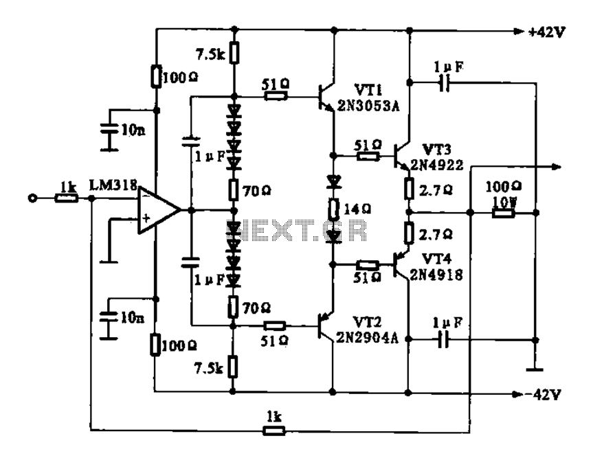
The current amplifier circuit configuration is illustrated in the figure. It consists of a two-stage operational amplifier, the LM318, arranged in a complementary push-pull amplifier configuration, which exhibits low output resistance and possesses load capacity features. The current amplifier circuit...
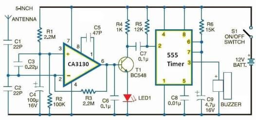
Cellular phone detector circuit schematic using common electronic parts The cellular phone detector circuit is designed to identify the presence of a cellular phone within a specified range. This circuit utilizes basic electronic components, making it accessible for hobbyists and...
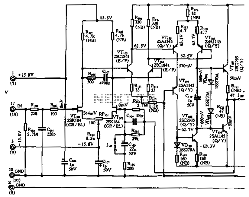
The circuit features a differential input stage that implements differential voltage amplification, forced differential voltage amplification, and a complementary push-pull amplifier output. It includes a bias circuit, a distortion servo circuit, and a protection circuit. The input preamplifier stage...
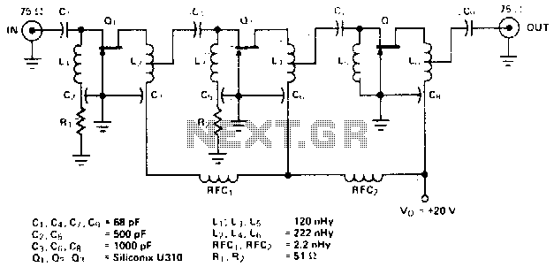
The amplifier circuit is designed for a center frequency of 225 MHz, with a bandwidth of 50 MHz at 1 dB, low input voltage standing wave ratio (VSWR) in a 75-ohm system, and a gain of 24 dB. Three...