
Low-Noise Microphone Amplifier (OP270E)
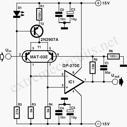
The microphone amplifier circuit described utilizes a differential amplifier configuration to effectively boost the weak audio signal from a microphone to a usable line level. The core component, T1 (T-03E), is a low-noise dual transistor that minimizes noise and distortion, critical for maintaining audio fidelity. The circuit employs T2 and LED D1 to establish a constant-current source, ensuring stable operation of the input stage, which is vital for consistent signal amplification.
The operational amplifier used in the circuit, the OP-270E, is known for its low noise characteristics, making it suitable for audio applications. It amplifies the differential signal extracted from the collectors of the dual transistor, producing a clean analog output. The design allows for a broad bandwidth, accommodating frequencies from 1 Hz to 20 kHz, which encompasses the entire audible range. The low distortion rate of less than 0.005 percent within the audio spectrum ensures high-quality sound reproduction.
Moreover, the circuit is designed to utilize only one half of the OP-270E, leaving the other half available for use in a stereo setup, thus enhancing the versatility of the design. The power supply requirements are also practical, as it can operate with a symmetrical supply voltage ranging from ±12 V to ±15 V, a standard specification found in many audio equipment setups. This makes the microphone amplifier suitable for integration into existing audio systems, providing an effective solution for connecting low-output microphones to line-level inputs.The signal from a microphone is two weak for a standard line input. This low-noise DC-coupled microphone amplifier provides a solution for anyone who wants to connect a microphone to his or her hi- installation. As can be seen from the schematic diagram, a good circuit does not have to be complex. A differential amplifier is built around T1 (MA T-03E), which is a low-noise dual transistor. The combination of T2 and LED D1 forms a constant-current source for the input stage. A low-noise opamp (OP-270E) amplifies the difference signal that appears at the collectors of the dual transistor. The result is an analogue signal at line level. The bandwidth of the amplifier ranges from 1 Hz to 20 kHz. Within the audio range (20 Hz to 20 kHz), the distortion is less than 0. 005 percent. Since only half of the OP-270E is used, the remaining opamp could be used in the output stage of a stereo version.
The amplifier can be powered from a stabilized, symmetrical supply with a voltage between ±12 V and ±15 V. Such supply voltages are already present in many amplifier. 🔗 External reference
Related Circuits
Almost all DC amplifier circuits are utilized as the input stage of differential circuits. Many complementary symmetry circuits also employ a double differential complementary sub-circuit along with a constant current source for the input stage. The constant current source...
When the start switch is pushed, the output of the charger goes to 14.5 V. As the battery approaches full charge, the charging current decreases and the output voltage is reduced from 14.5V to about 12.5V, terminating the charging...
The input is AC coupled to the amplifier through capacitor C2, which blocks any DC signals that may also be present at the input. The combination of resistor Rl and capacitor Cl forms a low-pass filter, effectively eliminating unwanted...
This is a simple low-impedance preamplifier circuit diagram used to amplify an audio signal. The circuit operates with a 12V DC power source and is straightforward due to its minimal component count. The low-impedance preamplifier circuit is designed to enhance...
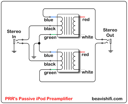
Construct a basic passive preamplifier for use with an iPod, Zune, or other portable media players. This device is particularly useful for enhancing audio quality in a car environment. A passive preamplifier is a circuit designed to amplify audio signals...
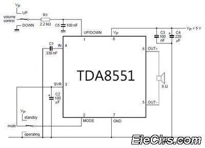
An amplifier with digital volume control can be designed predictably due to the simplicity of the circuit, which utilizes a single chip, the TDA8551. This series of mini amplifiers with digital volume control operates as a BTL (Bridge-Tied Load)...