
Automatic Room Power ControlCircuit CD4017 IC
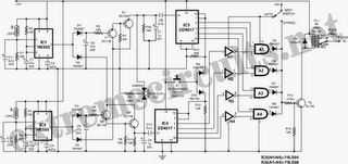
The Automatic Room Power Control Circuit utilizes an NE555 timer IC configured in a monostable or astable mode, depending on the desired functionality. The primary purpose of this circuit is to automatically control the power supply to a room based on ambient light levels detected by the LDRs.
In this circuit, two LDRs are strategically placed to sense the light intensity from different angles or areas within the room. As the light intensity changes, the resistance of the LDRs varies, which in turn affects the voltage at the input of the NE555 timer. When the light level drops below a certain threshold, the NE555 activates an output that can control a relay or a transistor, thereby switching on the power to the room's lighting or other electrical devices.
The circuit may include additional components such as resistors and capacitors to set the timing intervals and to stabilize the voltage levels. The output stage typically consists of a relay that can handle higher current loads, allowing for the control of multiple devices without overloading the NE555.
This circuit is ideal for energy-saving applications, ensuring that lights are turned on only when necessary and automatically switching off when sufficient natural light is available, thereby conserving electricity and enhancing convenience in everyday usage.The following circuit shows about Automatic Room Power Control Circuit Diagram. This circuit based on the NE555 IC. Features: uses two LDRs, use .. 🔗 External reference
Related Circuits
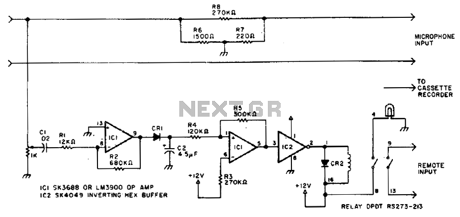
Amateurs do not have to miss the action while away from the rig. This circuit activates a tape recorder whenever the receiver's squelch is broken. After signal loss, the recorder will turn off following a slight delay. The described circuit...
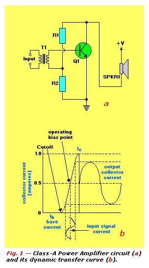
An audio power amplifier can enhance weak signals from devices like tuners, CD players, or tape decks to fill a room with sound. This article emphasizes the operating principles and circuitry of low-frequency power amplifiers utilizing bipolar junction transistors...
This project is designed to charge a pair of AA Nickel Metal Hydride (NiMH) or Nickel Cadmium (NiCd) cells using a laptop's USB port for power. It addresses the need for a convenient charging solution. Any USB port can...
You need a power supply for a project, but only have a DC adapter available, so you can't use my AC power adapter trick (Project 05). This little project came about because a reader had just this problem, and...
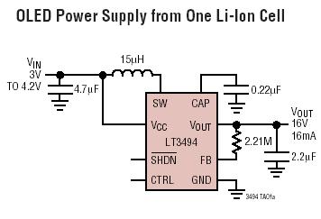
The LT3494 and LT3494A are low-noise boost converters that integrate a power switch, Schottky diode, and output disconnect circuitry. These devices utilize an innovative control technique that results in minimal output voltage ripple and high efficiency across a broad...
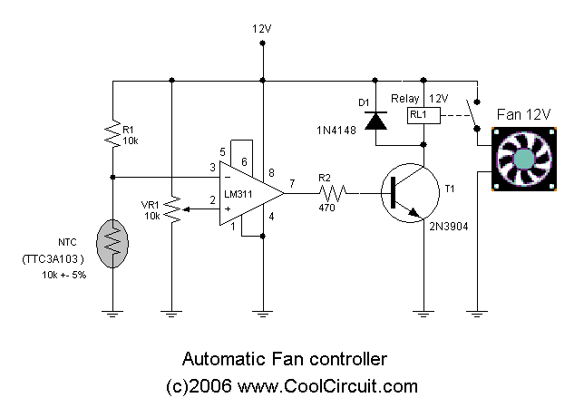
Automatic fan control circuit. This circuit turns a 12V DC fan or CPU fan on or off based on temperature readings. The temperature can be adjusted using VR1. The automatic fan control circuit operates by monitoring the temperature of...
Warning: include(partials/cookie-banner.php): Failed to open stream: Permission denied in /var/www/html/nextgr/view-circuit.php on line 713
Warning: include(): Failed opening 'partials/cookie-banner.php' for inclusion (include_path='.:/usr/share/php') in /var/www/html/nextgr/view-circuit.php on line 713