
Analog Switch for Oscilloscope

The circuit described involves an analog switch that is utilized for multiplexing signals between two channels, specifically channel 1 and channel 2. This switching occurs at the end of each sweep, indicating that the circuit is likely part of a time-based signal processing system, such as an oscilloscope or a similar device.
The controls mentioned provide significant functionality to the operator. The Dual Trace/Single Trace mode allows the user to select whether both channels are displayed simultaneously or if only one channel is active at a time. This feature is crucial for comparative analysis of the two signals.
Sync polarity control permits the user to adjust the synchronization of the displayed waveforms, ensuring that the signals can be aligned correctly for analysis. The sync level adjustment allows for fine-tuning of the trigger point of the waveform, which is essential for accurately capturing the desired portion of the signal.
The sync on + or - feature indicates whether the synchronization occurs on the rising edge or the falling edge of the waveform. This capability is vital for various signal types that may exhibit different characteristics in their transitions.
The overall design would typically include operational amplifiers for signal conditioning, analog switches (such as CMOS or transmission gates) for multiplexing, and a microcontroller or dedicated logic circuitry for managing the control signals and user interfaces. Power supply considerations and grounding techniques would also be critical for maintaining signal integrity across the multiplexed channels.The analog switch multiplexes between channel 1 and channel 2 at the end of each sweep. Controls include Dual Trace/Single Trace mode, sync polarity, sync level, and sync on + or - (rise or falling) edges. 🔗 External reference
Related Circuits
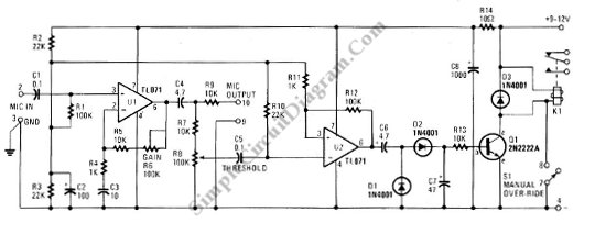
This schematic diagram below shows a circuit of a VOX Box (voice-operated switch). This circuit consists of a Schmitt trigger, a relay driver, and a microphone. The VOX Box circuit operates as a voice-activated switch, utilizing a microphone to detect...
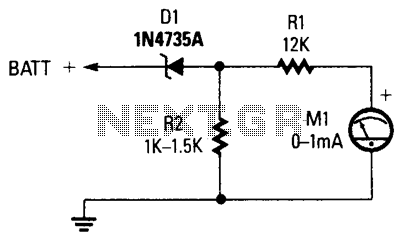
The circuit comprises a 0-1 mA meter (M1), a 6.2 V zener diode (D1), and a 12 kΩ, 1% resistor (R1). A load resistor (R2) is included in the circuit for the zener diode, with a non-critical value ranging...
This device uses the second method, which requires about 100 times less parts, but adds motion detection to switch cameras. The usual way to detect motion is to store a complete video frame and then look for changes on...
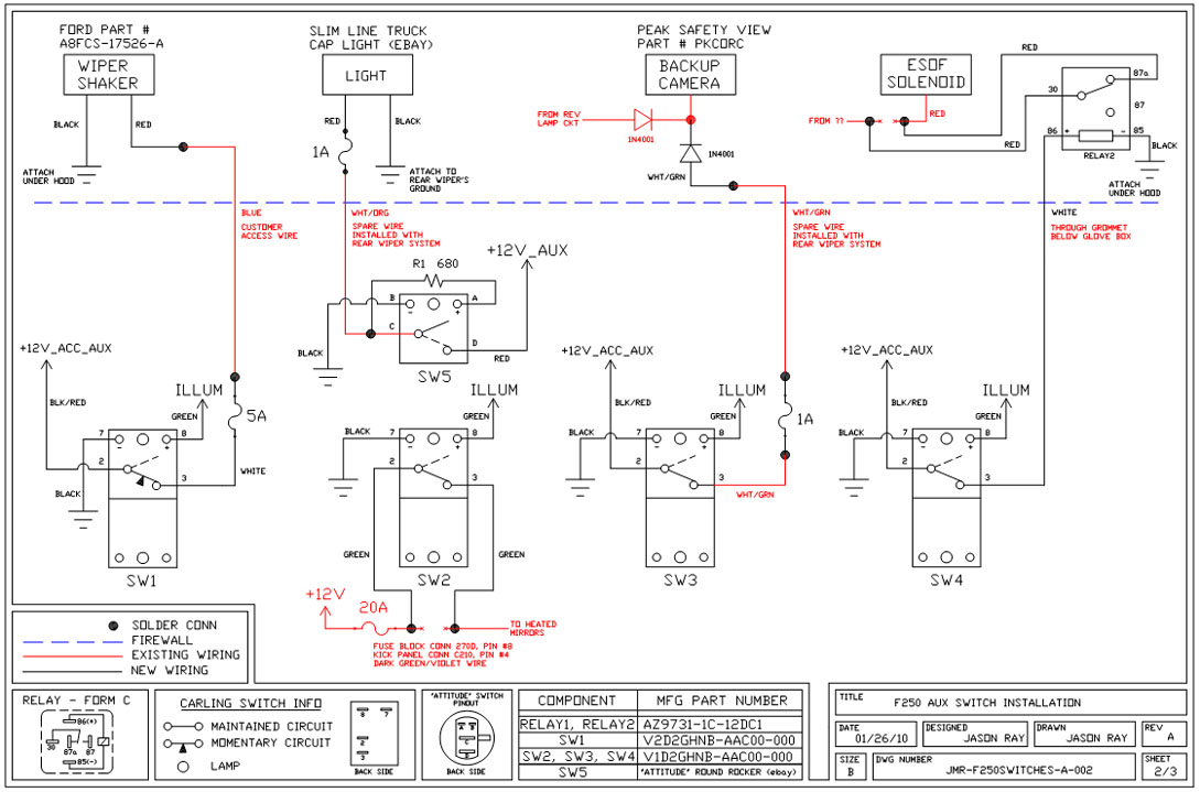
A +12V switched wire was routed back to the camera wiring and connected at the same point as the reverse lights. This configuration allows either the reverse lights or the switch to activate the camera. The critical component in...
The AD8205 can be utilized to create a high-side current sensing circuit with a low-side switch. In this configuration, an inductive load (such as a solenoid) and a resistive shunt are incorporated. The resistive shunt is positioned on the...
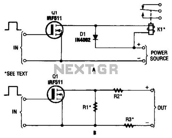
The hexFET can switch DC power to relays, motors, lamps, and various other devices. This configuration can also be utilized to switch resistors in and out of a circuit. R1, R2, and R3 represent resistive loads that can be...