
Review of Arduino DAC solutions

An R-2R ladder DAC consists of a network of resistors arranged in a specific configuration, where R and 2R denote the resistor values. The digital input signals control the output voltage by switching the resistors in the ladder configuration, effectively creating a variable voltage output. The absence of an output buffer can lead to inaccuracies in the output signal, especially when driving varying loads. By integrating an operational amplifier as a buffer, the output impedance is reduced, and the DAC becomes less sensitive to the load it drives, thus improving the fidelity of the output signal.
The LM358 operational amplifier is well-suited for this application due to its capability to operate on a single supply voltage, making it convenient for battery-operated devices or systems with limited power supply configurations. When using a voltage divider with a 5V supply, it is crucial to calculate the resistor values carefully to ensure that the output voltage remains within the desired range without compromising the signal integrity.
The Atmega microcontroller's internal pull-up resistors provide a convenient means to implement the R-2R ladder DAC with minimal external components. However, the variability in the pull-up resistor values can introduce inaccuracies in the output voltage. The maximum frequency of 500kHz indicates that while the DAC can switch rapidly, the settling time of 20ms may limit its application in high-fidelity audio systems.
For applications requiring higher resolution, the use of PWM outputs with a low-pass filter is a practical solution. The filter smooths out the PWM signal, effectively converting it into a continuous analog voltage. The ability to combine multiple PWM outputs enhances the resolution, allowing for more precise control over the output signal.
The SPI interface with the MPC4921 DAC chips represents a more efficient approach to generating analog signals, particularly in applications where multiple channels are required. This method reduces the number of GPIO pins needed, freeing them for other tasks. The integration of audio playback capabilities using the MCP4921 DAC chip highlights the versatility of Arduino platforms in audio applications.
Overall, the combination of R-2R ladder circuits, PWM techniques, and dedicated DAC chips provides a range of options for generating analog signals with Arduino, catering to various applications from simple control systems to complex audio synthesis.An analog output for my Arduino. The most common way to build a DAC is to use a R-2R ladder circuit. However, this DAC has no output buffer, which would make this circuit a bit more reliable and working with all kinds of loads. For the best results, you should use an output buffer in the DAC. The buffer separates your R-2R ladder from the load you connect it to and makes the result non load dependent.
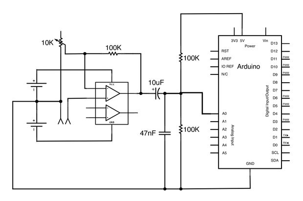
Here`s maybe the best tutorial I`ve seen for a R-2R DAC with an output buffer. It uses a common LM358 operational amplifier that can be driven from single supply. Note that in order to get the full output range to work with this circuit, you need to have a higher than 5V supply for the LM358. Of course, another way to get around this problem is to use a 5V supply but put a simple voltage divider in front of the op amp.
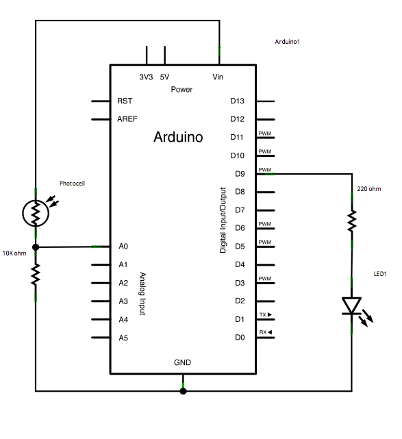
Then you`ll get lower than 5V output but don`t lose fidelity. A very clever solution utilizing the integrated pullup resistors on the Atmega chip. You need only 1 resistor and as many output pins as you want bits. The output is a bit crude but 500kHz could be reached. The internal pullups are specified to be minimum 20kohms and maximum 50kohms so the result might not be the most accurate. This design uses only two output pins, and the circuit is fairly simple, utilizing an op amp. The max settling time is 20ms, which is way too low for audio output. But the settling time could be enhanced with a circuit modification. Of course, you can also use the PWM outputs to get an analog output signal from the Arduino. Just put a low pass filter after the PWM output to get a nice & smooth output with a frequency range up to 16kHz, according to this Lab3 experiment.
This is a good explanation on how to combine two PWM outputs in order to double the bit resolution. So combining two 8-bit arduino PWM outputs you can get a 16-bit PWM output! Remember Arduino`s limits if you plan on going down this road. I mean, the Atmega chip is just 8-bit. Stepan Schulz used SPI to interface two MPC4921 12-bit DAC chips. This saves you pins compared to the R-2R ladder. Using the onboard SPI of the Arduino like Stepan, you need 5 pins, but you can save one (maybe even two) if you code the SPI code by hand. Adafruit industries` Wave shield is an audio shield for Arduino that also uses the MCP4921 SPI DAC chip.
You can play back 12-bit 22kHz wav files. This means the maximum output frequency is 11kHz. Another shield that uses the MCP4921 DAC chip. This one`s quite cool, it`s a monophonic synthesizer with MIDI input and the synth engine has an attack / release generator and a cool filter! Proves that the Arduino can be used to generate synth sounds. 🔗 External reference
Related Circuits
This example demonstrates a technique for calibrating sensor input. The Arduino takes sensor readings for five seconds during startup and tracks the highest and lowest values obtained. These sensor readings during the first five seconds of the sketch execution...
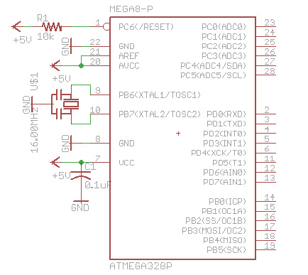
There are many bare-bones Arduinos available on the internet. Most of them are assembled on a solderless breadboard and utilize an ATmega168 (or ATmega328) microcontroller with an Arduino bootloader, a resonator (which may have built-in capacitors or require two...
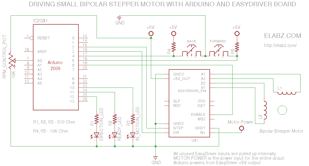
A simple circuit designed for testing bipolar stepper motors or for manual positioning using stepper motors. Schematics, Arduino sketch, and video are available. This circuit serves as a versatile tool for both testing and controlling bipolar stepper motors, which are...
The described device is used to convert the digital signal format S/PDIF (AES3) to analog. It can be used for any device with uncompressed digital audio output (desktop CD or DVD, minidisk, sound card PC CD-ROM). Separate transmitter can...
This Arduino-powered vocal effects box pitch shifts and distorts incoming audio signals to produce a wide variety of vocal effects. This project serves as an experiment with real-time digital signal processing using Arduino. It samples an incoming microphone signal...
The approximate center of the base was marked, and a hole was drilled large enough to accommodate a setscrew for the servo armature. The armature was then secured to the underside of the base using hot glue, ensuring that...