
Arduino TV weather channel
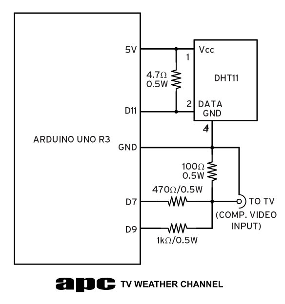
The circuit involves several key components and connections to facilitate the composite video output and sensor integration. The Arduino Uno serves as the central controller, interfacing with the DHT11 temperature and humidity sensor. The DHT11 sensor requires a power supply of 5V, connected to pin 1, while pin 4 is grounded, and pin 2 outputs the data. A 4.7kΩ pull-up resistor is connected to pin 2 to ensure reliable data transmission. This data is fed into pin 11 of the Arduino Uno, allowing the microcontroller to read temperature and humidity values.
For video output, pin 7 of the Arduino is utilized to send the visual data to the display, while pin 9 generates the synchronization pulses necessary for the TV to correctly render the image. A 100Ω resistor is connected to ground at the video output to enhance the signal integrity and improve compatibility with the TV's composite video input. The project can be constructed on a standard breadboard, and an RCA socket is required for the video output connection.
The software implementation leverages the Arduino-TVout library, which simplifies the process of converting text and graphics into video signals. The library manages the pixel data in RAM, allowing for the display of text strings at specified coordinates on the screen. The command `print(x, y, "string");` is used to position and render text, where `x` and `y` denote the pixel coordinates. For graphical output, images must be processed into a compatible format, typically requiring conversion to a 1-bit depth BMP image, which is then translated into a C array for use in the Arduino sketch.
The overall design demonstrates the capability of the ATMEGA328P microcontroller to produce a functional video output while managing limited resources effectively. The integration of the DHT11 sensor further showcases the versatility of the Arduino platform, enabling the display of real-time environmental data alongside visual graphics. This project serves as an educational demonstration of both hardware and software principles in microcontroller-based applications.So far the idea has been to show you how the Arduino Uno board and its Atmel ATMEGA328P microcontroller can interact fairly simply with the outside world. This time we`re simplifying the electronics but ratcheting up the demands on the microcontroller by aiming to hook up our Arduino Uno to the most complicated display output option available: tel
evision. Composite video is the least loved video connection system by video purists because it delivers the worst quality (actually RF-modulated video is worse but that`s another story). Although composite video uses just a two-wire system it`s actually surprisingly complex because it has to incorporate not only the vision data but also the synchronisation information all on the one video signal.
The vision data is the analogue representation line by line of what you see on the screen while the synchronisation pulses tell the display device where on the screen to display that data. Because we have limited processing power our Arduino can`t produce colour and it only has a low 120 x 96-pixel resolution.
However that`s still enough to produce text and graphics and we`re going to make use of that in this project. If you go back far enough you`ll remember home computers like the Commodore 64 the Tandy TRS-80 and others all of which had processors barely pushing 1MHz but offered colour composite video output you could connect to almost any TV screen.
Those computers used considerably more electronics to create the composite video signal. We`re going to do to it with just two resistors. The two resistors connect directly to two pins on the Arduino board pin 9 produces the sync pulses while the video is output via pin 7. Again like last month we`re standing on the shoulders of giants and using an Arduino library Arduino-TVout to generate the video and sync information.
While you don`t need to know how it works internally it`s well worth understanding just a little about composite video so you get a real feel for just how hard the ATMEGA328P has to work. Composite video for Australian PAL-standard TVs is displayed at the field rate of 50fps or 50Hz. In each field there are 312. 5 horizontal TV lines so that if each field has to take one 50th of a second or 20 milliseconds (ms) those 312.
5 lines have to be created in that 20ms at a rate of one line every 64 microseconds (64G‚ µs). Not every one of those lines ends up being visible 24. 5 lines are used for blanking` (getting the start of the next field to sync up correctly). In practice the horizontal resolution of the detail we can get into a TV line boils down to how many individual pixels we can generate in 64G‚ µs. Unlike modern CPUs the ATMEGA328P runs a fixed 16MHz clock rate or a clock cycle every 62. 5 nanoseconds (ns). Compared with the line rate of 64G‚ µs it works out that we get 1024 clock cycles per TV line. But if we have that many clock cycles why are we only getting 120 pixels on a line and why only 96 lines in a frame Well we`re hitting up against another of the ATMEGA328P`s limitations.
In order to display pixels on the screen those pixels have to be stored somewhere so they can be quickly retrieved and drawn in each frame. That means storing them in memory. The ATMEGA328P may have 32KB of flash memory but it only has 2KB of RAM. Given we`re using monochrome video only each pixel only requires 1-bit of storage so we actually have 16Kb of RAM to play with.
Multiply 120 by 96 and you get 11520 pixels we need to store which takes up 1440 bytes of RAM. The problem is you also need RAM to run your sketches every integer variable requires 2 bytes of RAM every string needs 1 byte per character. The highest 4:3 aspect ratio resolution 2KB of RAM could store is only 145 x 109 pixels and that`s only if we didn`t need RAM for anything else.
In the end it`s a compromise given the resources at our disposal. Still you have to remember the ATMEGA328P was never designed to produce video so huge kudos goes to Myles Metzler the developer of the TVout library for getting us this far in the first place. By comparison the brand new Arduino Due which runs a 32-bit ARM Cortex-M3 processor has 96KB of RAM to play with which is enough for 1000 x 750 pixels plus a decent 84MHz clock rate.
That might have you asking why we`re sticking with this old 8-bit microcontroller. Putting it simply the Arduino Uno is the ideal way to learn about microcontrollers it`s very stable simple to use easy to program harder to blow up and a fraction of the cost of a Due. One thing we want some of that leftover RAM for is to gather and display the results from our DHT11 temperature/humidity sensor.
We introduced this last month with the seven-segment display version of our weather station but by creating a video output we can greatly reduce the component count get the Arduino to read the sensor and output the data on a video signal it generates. That`s not bad going for an old 8-bit micro! If you take a look at the circuit diagram it`s pretty simple. We`ve taken the DHT11 sensor applied 5V to pin 1 grounded pin 4 and taken the data from pin 2 with the 4.
7kohm pull-up resistor connected to it. This data is fed into pin 11 on the Arduino. At the same time the video output (the data you actually see) comes off pin 7 and the sync pulses (the data that locks the picture on the screen) come from pin 9. And that`s it for the hardware. The 100ohm resistor to ground at the output is there to provide better loading matching to your TV`s composite video input.
You can use a standard breadboard on which to build the circuit although you`ll need an RCA socket for the video output. If you`re feeling confident you can take a DuPont wire like we`ve used here cut it in half pull off about 3mm of the insulation and solder each half to the socket connection points.
If that sounds too hard grab a couple of alligator test clips and use them instead. However if you`re seriously interested in electronics and building/hacking stuff you`ll eventually need to learn how to solder. We`re not going to reinvent the wheel here there are plenty of soldering tutorials online. The one at Instructables isn`t bad. With practice you should be able to do a good solder joint within three seconds. The single biggest tip I can give is to keep everything clean skin oil oxidises on component leads which can stop solder from wicking onto the lead and causes a cold solder joint.
If I`m using components or tinned copper wire that`s been lying around for a while I use a cheap kitchen scouring pad to clean up the wire or lead just enough to shiny it up and then the solder takes to it like a duck to water. As you may have guessed by skimping right down on the hardware we`re actually making the Arduino Duo do a heck of a lot in software.
To make it easier to code we`ve put the whole thing our sketch along with the TVout and DHT11 libraries together into a single. ZIP file which you`ll find on our Arduino web page. Download the file unzip it and copy the apc_03_tvweather` folder to your Arduino sketch folder and the contents of the libraries` folder to your computer`s Arduino_1.
0. 1libraries` folder. Once that`s done start up the Arduino IDE (you can download it from arduino. cc/en/Main/Software ) and load up the apc_03_tvweather. ino` sketch file. Again we`ve commented on much of the code to give you an idea of how it works but truth be told our sketch is quite simple: the hard work is carried out by the DHT11 and TVout libraries. We`re not going to go through it here (an explanation would be a whole other topic) but keeping it simple the TVout library takes our text information turns it into pixels stores it in RAM retrieves it line by line and then turns it into a video display which it then piggybacks onto the video synchronisation pulses and sends out to the RCA socket and your TV.
And that`s the short explanation! What`s so great about the TVout library is that it doesn`t require you to do anything complicated like poke your text as individual pixels into specific RAM locations. Instead it`s surprisingly simple (at least for text) thanks to its print command: print(xystring); where x and y are the x` and y` coordinates from the top-left corner and string is the text you want to display on the screen.
So for example print(1012G ‚¬ hello worldG ‚¬) would put the text string hello world` on the screen starting 10 pixels from the left and 12 pixels from the top of the display window. You`ll have noticed the APC TV weather channel splash image this is a bit more complicated to create.
Arduino Uno has no image compression support and no JPEG or BMP handling but it understands raw pixels. Here`s what you need to do. Start off with a BMP image 120 x 96-pixels or less and reduced to 1-bit (line art) bit depth. You can do this in most photo/image editor apps from GIMP to Photoshop. The next task is to convert it into a C+/source code array and you can do that with the Image2Code app.
Launch the app and browse for your image. Select the second option from the right (MSB ”-LSB`) tick the Invert Image` checkbox on the bottom-left and click the Convert` button. Windows Notepad will then launch and give you a C+ array of data. If you look at the Arduino IDE after loading up our APC_03 sketch open up the apclogo. cpp` tab and you`ll see a similar array with hexadecimal numbers. Copy the data from Notepad to the apclogo. cpp` tab and overwrite the original array. Make sure you remove the parentheses { and } at the start and end of each line along with the empty lines between each array line.
The last thing you need to do is set the image dimension at the very top of the apclogo. cpp` file. Simply change the 104 and 42 numbers to match the horizontal and vertical dimensions of your original BMP image (any decent image editor will tell you this information). Save it and when you launch the sketch in your Arduino Uno provided you have the TV circuit wired correctly you should see your image appear on your TV screen.
What we`re doing is storing the image as raw pixels in flash memory of which we have buckets compared to RAM. Another thing that`s quite interesting with the TVout library is that you actually get to set the output resolution.
Keeping in mind the 2KB RAM limit you can choose the screen resolution using the begin(modexy) command. So by using TV. begin(112096) we`re telling the library we want to create a PAL-standard video output (1 for PAL 0 for NTSC) with 120 pixels horizontally by 96 vertically.
To change the resolution you just change the x` and y` values. Just be sure that the x` size is divisible by eight or it won`t work. 🔗 External reference
Related Circuits
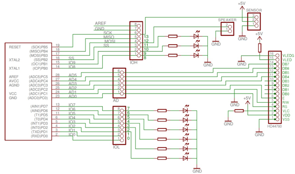
Required components include an Arduino Uno, an HD44780 Character LCD, a PING))) Ultrasonic Distance Sensor, a speaker cone from an old computer, a breadboard, wires, resistors, colored LEDs, and Arduino software. The provided schematic illustrates the parking sensor circuit....
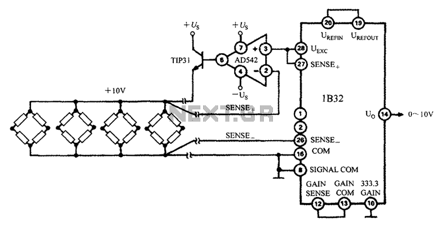
The 1B32 application circuit features multiple pressure sensors as illustrated in the figure. Excitation power is supplied through the AD542, which is followed by a TIP32 transistor that drives multiple bridge sensors. The AD542 operates as a Bi-FET in...
With the rapid development of the social economy, the demand for electric energy continues to increase. In light of the diminishing availability of non-renewable energy sources, such as fossil fuels, many countries are recognizing the importance of energy conservation...
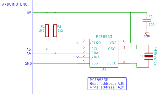
The Arduino displays the time and date on an optional LCD and in the Arduino IDE serial monitor window. A PCF8563 real-time clock (RTC) integrated circuit (IC) is utilized to generate the time and date. The time and date...
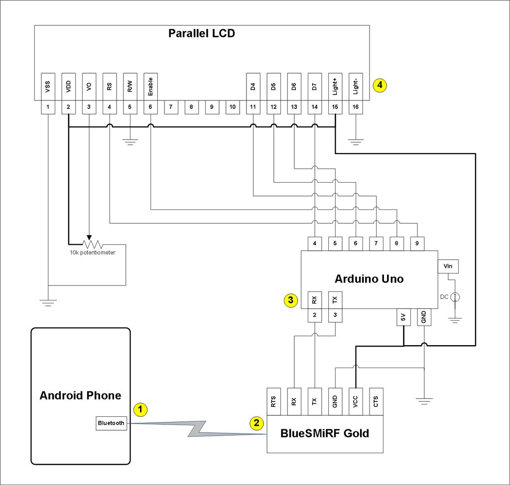
This project involves a modification of the Google Android sample app known as Bluetooth Chat, allowing users to type a message in the Android app and display that same message on an LCD connected to an Arduino Uno. The...
The first prototype PCB has been completed, but concerns arise regarding the heat generated when utilizing the BMS at maximum power in an ultralight hybrid electric vehicle application. At 30A continuous and 50A burst, nearly 20W of loss occurs....