
Astable multivibrator

The astable multivibrator circuit is an essential building block in electronic applications, primarily functioning as an oscillator to generate square wave signals. The operation of the circuit can be divided into two main phases: charging and discharging of the capacitors involved. During the charging phase, when the switch is closed, capacitor C2 begins to charge through resistor Rz, which sets up the necessary conditions for the transistors to operate in a feedback configuration. The positive feedback loop created by the coupling circuit ensures that once VT1 is turned on, it will continue to drive VT2, which in turn reinforces the conduction of VT1.
As the voltage across C2 rises, it eventually reaches a threshold level that causes the base of VT2 to become forward-biased, allowing it to conduct. This conduction leads to a rapid increase in current, which further charges C2 until it reaches a point where the feedback mechanism is disrupted, causing VT2 to turn off. The transition from conducting to non-conducting states creates the oscillation, with the time period of the oscillation being determined by the values of the resistors and capacitors in the circuit.
In practical applications, the frequency of oscillation can be adjusted by varying the resistance of Rz or the capacitance of C2. The astable multivibrator can be employed in various applications, including clock pulse generation for digital circuits, tone generation in audio devices, and timing applications in microcontroller systems. Understanding the behavior of each component in the circuit is crucial for designing effective pulse generators that meet specific frequency and duty cycle requirements. Astable multivibrator using too many electronic devices, widely used in the pulse signal generating circuit, which works as 17-18 in FIG. From the figure shows, with A coupling circuit between two transistors VT1 and VT2 to C2 and Rz way connected. The output VT2 VT1 sent out through the coupling circuit B (C, R,) form a positive feedback input, thus forming the oscillator circuit. Figure l in the transistor VT1 Sl replaced with a switch to VT1 VT2 omitted from the coupling circuit B (Ci, Rl), it now looks like Figure Figure (a) is a case of switching off sl, VT2 base from the power supply through R2 with a forward voltage, so that V-12 is turned on.
At this time, the electrical path of the dashed line is current for charging the capacitor C2. Then the switch is closed sl t in FIG. (B) in Fig. Since the capacitor C2 is charged at this time, the voltage is cut o. So switch closure moment is equivalent to VT2 base plus negative pressure, so that VT2 end. Figure (b) in the direction of the broken line is the capacitance c7, the charge discharging direction to, then VT2 base voltage changes from negative to positive, VT2 then turned on again.
Related Circuits
Multivibrators are two-state devices that are extensively used in digital electronics. Bistable multivibrators, also known as flip-flops, serve as fundamental memory elements. Multivibrators can be categorized into three primary types: astable, monostable, and bistable. Each type has distinct operational characteristics...
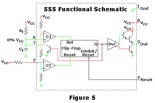
The SE555/NE555 timer was first introduced by the Signetics Corporation around 1971. Pin connections and functions are as follows: Pin 1 (Ground) - This pin serves as the ground or common pin, representing the most negative supply potential of...
This is one of the most basic 555 circuits. This circuit is part of the chip's datasheet, complete with the math needed to design to specification, and is one of the reasons a 555 is referred to as a...
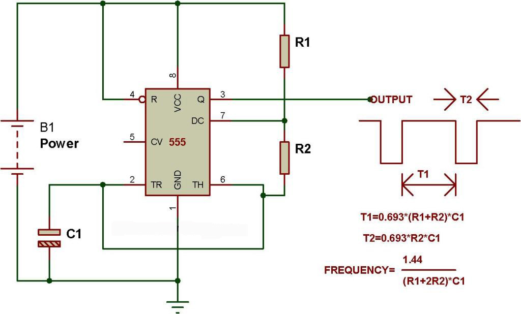
The schematic presented originates from buildcircuit.com. This circuit functions as a music generator, infrared transmitter, and LED blinker, depending on the values of R1, R2, and C1. A minor modification to the previous circuit allows it to operate as...
The circuit remains in a stable state until a triggering signal is applied to its input. Upon receiving the triggering signal, the output transitions from a stable state to a quasi-stable state and returns after a specified time period,...
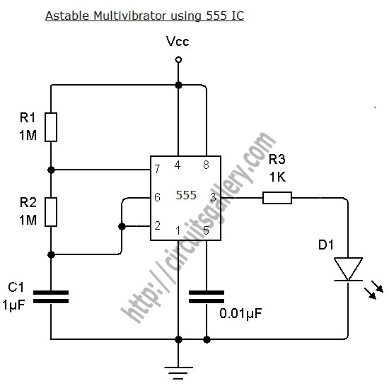
An astable multivibrator can be designed using a 555 timer IC, operational amplifiers, or transistors. The 555 timer IC provides accurate time delays ranging from milliseconds to hours, with the frequency of oscillation adjustable through simple modifications. This is...