
Astable Multivibrator
The astable multivibrator circuit is a fundamental application of bipolar junction transistors (BJTs) configured to produce a continuous square wave output. This circuit does not have a stable state; instead, it oscillates between two unstable states, which results in the alternation of LED illumination.
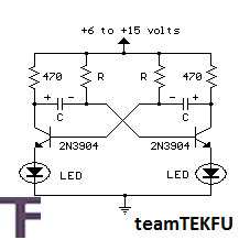
In this configuration, two NPN transistors are used, each connected to a resistor-capacitor (RC) timing network. The timing network consists of two resistors and two capacitors, with each transistor controlling one LED. The charging and discharging cycle of the capacitors through the resistors determines the oscillation frequency. When one transistor turns on, it allows current to flow through its associated LED, causing it to light up, while simultaneously turning off the other transistor and extinguishing its LED.
The choice of a 470-ohm collector load resistor is crucial as it sets the maximum current flowing through the LEDs, ensuring they operate within safe limits without being damaged. The 20-milliamp current is suitable for standard 5mm LEDs, providing adequate brightness without overheating.
The frequency of oscillation can be adjusted by varying the values of the resistors and capacitors in the circuit. Using smaller resistor values or capacitors will result in a higher frequency, allowing for more rapid alternation between the two LEDs. This feature enables customization of the flashing rate to suit specific application requirements.
For applications requiring different brightness levels or color combinations, various types of LEDs can be used, and they can be wired in series with the collector resistors. Additionally, different transistor types can be selected based on the desired switching speed and current handling capabilities, which can further enhance the circuit's performance. This flexibility makes the astable multivibrator circuit a versatile choice for LED flashing applications in various electronic projects.This is an Astable Multivibrator Circuit to alternately flash two LEDs. The R and C Values determine the frequency and the 470 ohm collector load resistors set the current to about 20 miliamp, when the circuit is operated at 12Volts. Frequncy is about 1Cylce per second using 22uF capacitors and 47K resistors. Smaller R and C Values will increace Freq uency. The LEDs may also be wired in series with the collector resistors and other transistors can be used. 🔗 External reference
Related Circuits
The resistor in series with the LED in the collector circuit of transistor T1 must be 470 ohms, not 470k. To connect a 24V-3W bulb, it is important to note that the resistance of this bulb when lit is...
This circuit is basically simple and easy to build, it uses two transistors as active components and a few passive components like resistors, capacitors and two LEDs. The circuit makes use of the MPS2222 transistor. You can use any...
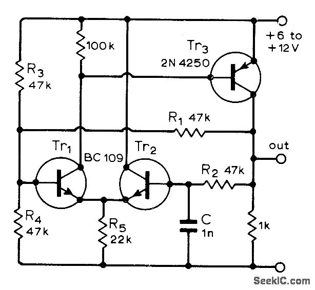
A single-capacitor circuit exhibits reliability across a wide range of temperatures, voltages, and transistor gains. The frequency varies by only 0.05% when the supply voltage changes between 6V and 12V. Timing adjustments can be made using resistors R1 and...
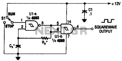
Two gates of the Quad 4093 are utilized to create an oscillator. The resistor (R) can range from approximately 5 kΩ to around 10 kΩ. The capacitor (Cx) can vary from about 10 pF to higher values, with the...
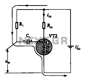
When VRI is off, 0 [2 is activated, allowing current to flow through RJ and Ci. When VT1 conducts, charging of C1 begins, causing it to discharge. This results in an inverting charge on C1, making the voltage positive,...
The astable multivibrator is a specific type of relaxation oscillator that utilizes in-phase feedback provided by a separate transistor. Initially constructed using vacuum tubes, this circuit gained widespread popularity and was extensively utilized in early computers and television sets...