
astable multivibrator transistors

The astable multivibrator circuit is a fundamental component in digital electronics, often used for generating square waves or clock pulses. Its operation relies on the interplay between two bipolar junction transistors (BJTs) or field-effect transistors (FETs), which are alternately switched by the charging and discharging of capacitors.
In a typical configuration, the circuit consists of two transistors (Q1 and Q2), two resistors (R1 and R2), and two capacitors (C1 and C2). The transistors are connected in such a way that the output of one transistor feeds into the base of the other, creating a feedback loop. The resistors control the rate at which the capacitors charge and discharge, thus influencing the frequency of oscillation.
When the circuit is powered, one of the transistors will initially turn ON due to slight differences in transistor characteristics or initial conditions. This transistor will quickly saturate, pulling its collector voltage low and allowing the associated capacitor to discharge. As the capacitor discharges, it generates a negative voltage that eventually turns OFF the first transistor. Simultaneously, the second transistor begins to turn ON as its base-emitter junction receives sufficient voltage from the charged capacitor.
The oscillation continues as the capacitors alternate between charging and discharging, with the time periods of each state determined by the RC time constants of the respective capacitors and resistors. The frequency of oscillation can be adjusted by varying the resistor or capacitor values, allowing for flexible applications in timing circuits, frequency generators, and pulse-width modulation systems.
In summary, the astable multivibrator is a self-sustaining oscillator, producing square wave outputs without the need for external triggering, making it a versatile tool in various electronic applications.An Astable Multivibrator or a Free Running Multivibrator is the multivibrator which has no stable states. Its output oscillates continuously between its two unstable states without the aid of external triggering.
The time period of each states are determined by Resistor Capacitor ( RC ) time constant. In the above diagram we can find two transisto rs which is wired as a switch. Please do read the article Transistor as A Switch. When a transistor is ON, its collector and emitter act as a short circuit. But when it is OFF they acts as open circuit. So in the above circuit when a transistor is in OFF state its collector will have the voltage Vcc and when it is ON its collector will be grounded. When one transistor is ON the other will be OFF. The OFF time of transistor is determined by RC time constant. When the circuit is switched on, one of the transistor will be more conducting than the other due imbalance in the circuit or difference in the parameters of the transistor.
Gradually the more conducting transistor will be driven to Saturation and the less conducting transistor will be driven to Cutoff. Q2 is OFF due to the -ive voltage from the discharging capacitor C1 which is charged during the previous cycle.
So the OFF time of Q2 is determined by R1C1 time constant. When the Capacitor C1 charges to a voltage sufficient provide base emitter voltage of 0. 7V to the transistor Q2, it turns ON and capacitor C2 starts dischargeing. The negative voltage from the capacitor C2 turns off the transistor Q1 and the capacitor C1 starts charging from Vcc through resistor R and base emitter of transistor Q2. Thus the transistor Q2 remains in ON state. 🔗 External reference
Related Circuits

This circuit was first introduced by Signetics Corporation as the SE555/NE555 around 1971. Pin connections and functions are as follows: Pin 1 (Ground) is the most negative supply potential of the device, typically connected to circuit common when powered...
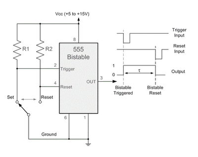
By applying a "LOW" signal to the Trigger input (pin 2) while the switch is in the Set position, the output state changes to "HIGH". Conversely, applying a "LOW" signal to the Reset input (pin 4) while the switch...
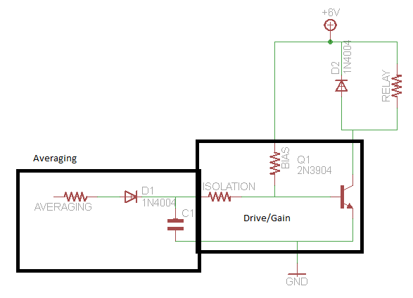
A circuit that activates a relay upon detecting audio pulses from one channel of an MP3 player. The intention is to synchronize recorded audio pulses with music to control a motor for mouth movement. For a stereo player, music...
The astable multivibrator presented in Wikipedia and college materials is depicted on the left side of the image. In contrast, the schematic on the right side is sourced from an LTSpice example. The right schematic is incorrectly drawn, and...
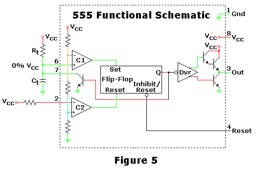
This is one of the most basic 555 circuits. This circuit is part of the chip's datasheet, complete with the math needed to design to specification, and is one of the reasons a 555 is referred to as a...
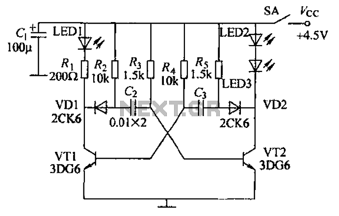
Transistors VT1, VT2, and associated RC components are configured to form a multivibrator. The multivibrator operates with resistors Ra and R4 serving as base bias resistors for VT2 and VT1, respectively. When the switch SA is closed after applying...