
bistable multivibrator using ic 555
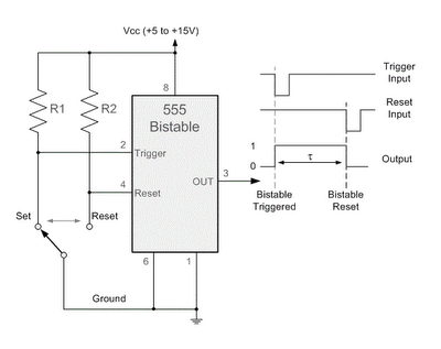
The 555 timer in bistable mode operates as a flip-flop, allowing it to store a binary state. In this configuration, the circuit utilizes two primary inputs: the Trigger and Reset. The Trigger input (pin 2) is activated by a negative edge signal. When this pin receives a "LOW" signal, it causes the output (pin 3) to switch to "HIGH", indicating that the circuit is in the Set state. The Reset input (pin 4) serves a complementary function; when it is pulled "LOW", it resets the output to "LOW", placing the circuit in the Reset state.
The bistable configuration of the 555 timer is particularly useful in applications requiring stable states, such as memory storage, toggle switches, or state retention in digital logic systems. The device remains in its current state until an appropriate input signal is applied, ensuring it does not change states accidentally due to noise or fluctuations in the input signals.
The timing characteristics of the 555 timer in this mode are determined by external components connected to the circuit, such as resistors and capacitors, which can influence the response time and stability of the output states. However, in its basic bistable operation, the 555 timer is capable of maintaining its output state without the need for continuous input signals, making it a reliable choice for various electronic applications.By taking the Trigger input (pin 2) "LOW", switch in Set position, changes the output state into the "HIGH" state and by taking the Reset input (pin 4) "LOW", switch in Reset position, changes the output into the "LOW" state. This 555 timer circuit will remain in either state indefinitely and is therefore bistable. Then the Bistable 555 timer is s table in both states, "HIGH" and "LOW". 🔗 External reference
Related Circuits
This simple LED flasher circuit will alternately turn ON and OFF two LEDs. The first LED will illuminate when the second LED is OFF for a certain duration, and then the process will repeat. The LED flasher circuit operates using...
Anyone who has designed circuits using the 555 timer chip has, at some point, wished for the ability to program longer timing periods. Timing intervals exceeding a few minutes are challenging to achieve due to the significant impact of...
This circuit diagram represents a remote control system utilizing DTMF (Dual Tone Multi-Frequency) signals. DTMF signals, generated by pressing numbers on a telephone keypad, serve as the control mechanism for the system. The DTMF tones are employed to modulate...
A low-cost light dimmer utilizing a silicon-controlled rectifier (SCR) and a triac. The flash-on effect is minimized by shunting the SCR with two 20K resistors, as per the guidance of Motorola Semiconductor Products Inc. The described light dimmer circuit...

Quasi square wave resonant converters, also referred to as quasi resonant (QR) converters, facilitate the design of flyback Switch Mode Power Supplies (SMPS) with diminished Electro Magnetic Interference (EMI) and enhanced efficiency. Due to their low noise generation, QR...
Below are a couple circuits you can use to produce a 32.768 KHz square wave from a common watch crystal. The output can be fed to a 15 stage binary counter to obtain a 1 second square wave. The...