
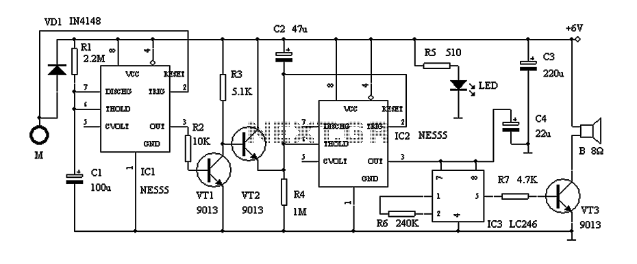
555 LED flasher

The circuit utilizes the 555 timer in astable mode, which allows it to continuously switch between high and low states, thereby causing the LED to flash. The timing of this oscillation is determined by the values of the resistors (R1 and R2) and the capacitor (C1) connected to the timer. The formula used to calculate the frequency of the oscillation is given by:
\[ f = \frac{1.44}{(R1 + 2R2) \times C1} \]
Where:
- \( f \) is the frequency in hertz,
- \( R1 \) is the resistance of the first resistor,
- \( R2 \) is the resistance of the second resistor,
- \( C1 \) is the capacitance in farads.
In this configuration, the charge and discharge times of the capacitor dictate how long the LED remains lit and how long it is off. The two additional capacitors connected to the timer (C2 and C3) may serve as decoupling capacitors to stabilize the power supply and filter out any noise that may affect the performance of the timer.
The current-limiting resistor (R3) connected in series with the LED ensures that the LED operates within its specified current range, preventing damage due to excessive current. The value of this resistor can be calculated using Ohm's law, considering the forward voltage drop of the LED and the supply voltage.
In summary, this circuit effectively demonstrates the versatility and functionality of the 555 timer in creating a simple LED flasher, with careful consideration given to the timing components and current limiting to ensure reliable operation.This circuit is built around one of the most popular timer integrated circuits, the 555 timer. It will flash the led on and of at regular intervals. From left to right, the two resistors and the capacitor set the time it takes to turn the led on or off, by changing the time it takes to charge the capacitor to trigger the timer. Next is the 555 timer, this is where all the work gets done to determine the time the led stays on and off.
It contains a complicated circuit inside, but since it is packaged in the IC it can be used as a simple component. The two capacitors that are right of the timer are just accessories so to speak, but are needed for the timer to work correctly. The last part is the resistor and the led, the resistor is there to limit the current on the led so that it won't burn.
🔗 External reference
Related Circuits
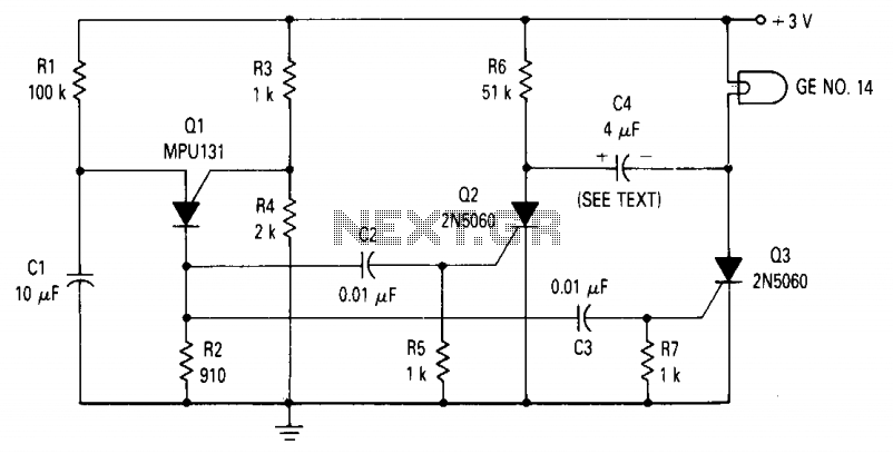
The circuit consists of a relaxation oscillator created by Q1 and an SCR flip-flop formed by Q2 and Q3. When the supply voltage is applied to the circuit, the timing capacitor C1 charges to the firing point of the...
The following circuit illustrates a portable NiCd battery charger circuit diagram. The portable battery charger is designed to facilitate the charging of nickel-cadmium batteries. The portable NiCd battery charger circuit typically consists of several key components, including a transformer, rectifier,...
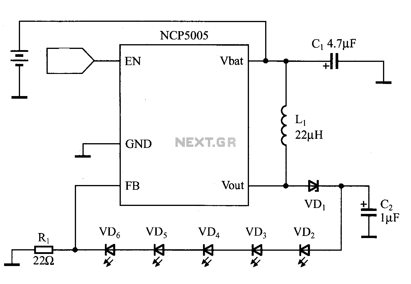
White LEDs can be connected in series or parallel, each method having its own advantages and disadvantages. A key disadvantage of the parallel connection is that the current and brightness of the LEDs do not automatically match. In contrast,...
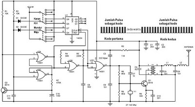
This circuit describes a door alarm system equipped with a time recognition feature. When the owner opens the door, it remains in a normal state for approximately 30 seconds without triggering the alarm. However, if the door is opened...
The following circuit illustrates a curtain control circuit diagram. This circuit is based on the 555 integrated circuit (IC). Features include a switch for manual control, the IC, and additional components. The curtain control circuit utilizes the 555 timer IC...
This indicator lets you see how much power an amplifier produces. The circuit uses an LM 3915, the logarithmic variation of the known IC LED VU Meter LM 3914. The circuit is connected directly to the speaker output of...