
Astable oscillator
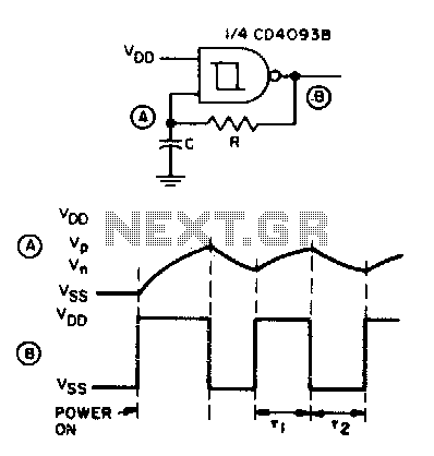
The described circuit functions as an astable multivibrator, characterized by its ability to produce a square wave output without the need for an external trigger. The operation begins with the capacitor C in a discharged state, ensuring that both the input and output are initially at ground potential. Upon applying power, the output voltage rapidly rises to Vdd, initiating the charging process of capacitor C through resistor R. The time constant of this charging phase is determined by the product of the resistance (R) and capacitance (C), which defines how quickly C charges to the threshold voltage V.
Once the voltage across capacitor C reaches the predetermined threshold (V), the output switches to low (Vss), marking the end of the charging phase. During this low state, capacitor C discharges through resistor R, dropping the voltage across it down to the lower threshold (Vn). This discharge phase also has a time constant dictated by the same R and C values.
As the voltage across C drops to Vn, the output transitions back to high (Vdd), thus restarting the charging cycle. This oscillation continues, with input A alternating between VP (the peak voltage) and Vn, effectively generating a square wave signal at the output. The self-starting feature of this circuit ensures that it begins oscillating immediately upon power application, making it suitable for applications requiring a stable clock signal or timing function. The design can be adjusted for different frequencies by varying the values of R and C, allowing for flexibility in various electronic applications.Before power is applied, the input and output are at ground potential and capacitor C is discharged. On power-on, the output goes high (Vdd) and C charges through R until V is reached; the output then goes low (Vss). C is now discharged through R until Vn is reached. The output then goes high and charges C towards VP through R. Thus input A alternately swings between VP and Vn as the output goes high and low This circuit is self-starting at power-on. 🔗 External reference
Related Circuits
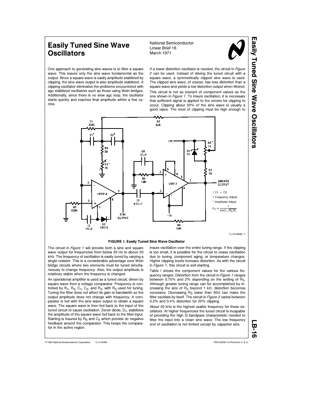
One approach to generating sine waves is to filter a square wave. This leaves only the sine wave fundamental as the output. If a lower distortion oscillator is needed, the circuit in Figure 2 can be used. Instead of...
Today, it is no longer necessary to use discrete components for constructing oscillators. Many manufacturers now offer ready-made voltage-controlled oscillator (VCO) integrated circuits (ICs) that require only a few external components to determine the frequency. An example of such...
Hand and body motions in proximity to the sensing antennas produce frequency changes in a Hartley oscillator operating at approximately 750kHz. The signal from this variable oscillator is mixed with a constant reference frequency in a ring modulator and...
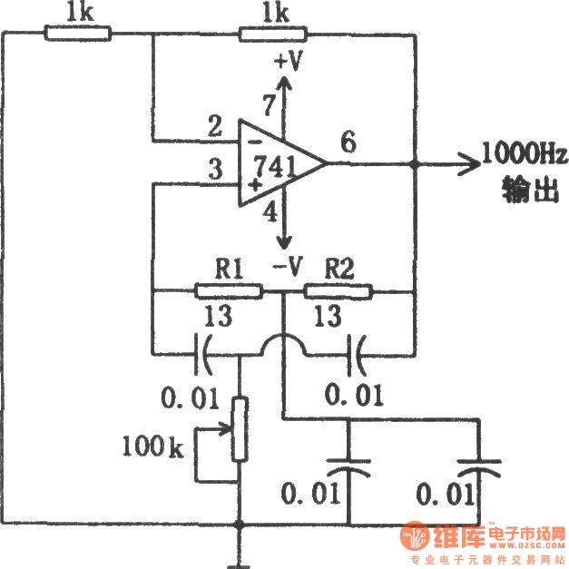
The circuit illustrated in the diagram is a 1 kHz sine wave oscillator circuit. Based on a double-T circuit configuration, it utilizes a standard 741 operational amplifier to generate a 1000 Hz sine wave output. The circuit begins oscillation...
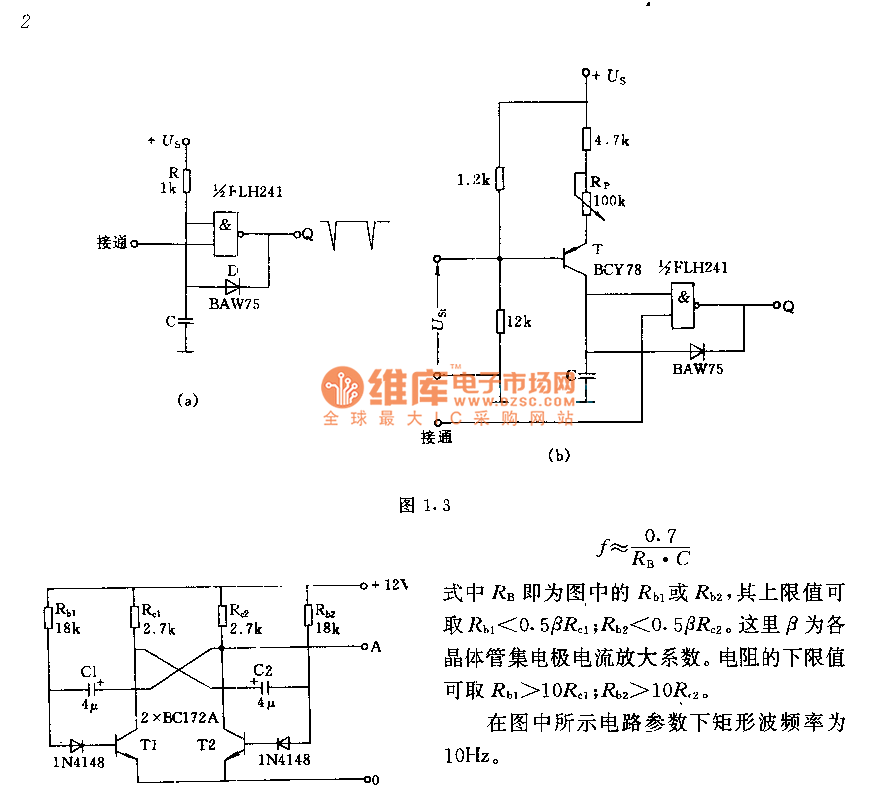
The circuit consists of two components whose parameters and models are designed to simultaneously generate a rectangular wave with a duty cycle of 1:1. The frequency is defined by the equation f = 0.7/(RB * C), where RB refers...
I am attempting to construct a Hartley oscillator using a bypassed common emitter configuration. The goal is to achieve oscillation at a frequency of 200 kHz with a peak-to-peak voltage of 2 V, utilizing a BC547B transistor. The Hartley oscillator...