
Audible Logic Probe with LM339
The audible logic probe operates based on the voltage levels present in TTL (Transistor-Transistor Logic) circuits. The primary components of the probe include a voltage comparator, a tone generator, and an audio output device, typically a small speaker or piezo buzzer.
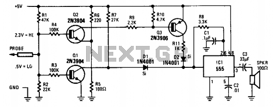
The voltage comparator is configured to compare the input voltage from the circuit under test against two reference voltages: 2 volts and 0.8 volts. When the probe tip is connected to a point in the circuit, the input voltage is fed into the comparator. If the voltage exceeds 2 volts, the comparator outputs a signal that activates the tone generator to produce a high-frequency tone, indicating a logic high state. Conversely, if the voltage falls below 0.8 volts, the comparator triggers the tone generator to produce a low-frequency tone, indicating a logic low state.
For proper operation, the probe is powered by a 5-volt source, which is typically the same voltage used in TTL circuits. The ground clip must be connected to the circuit's ground to ensure accurate voltage readings. The probe's design can be adapted for CMOS (Complementary Metal-Oxide-Semiconductor) circuits by adjusting the reference voltage levels to accommodate the different voltage ranges used in those applications.
In summary, the audible logic probe is a valuable tool for quickly assessing the logic state of various points in a TTL circuit, providing immediate auditory feedback that can enhance the efficiency of circuit testing and troubleshooting.When testing circuits with a logic probe, it is sometimes difficult to watch the LEDS on the probe to determine the logic state. With this probe the logic states are audible. This probe is designed for TTL circuits only but could be modified for CMOS. The way it works is as follows. The 5 volt power source will be the circuit under test. Clip the ground input of the probe to the ground of the circuit being tested. The other input lead is used to probe the different chips of the circuit being tested. Any input greater then 2 volts will be high and output a high tone through the speaker. Any input less then .8 volts will be low and produce a low tone through the speaker. 🔗 External reference
Related Circuits
The probe's input circuit detects the signal condition and generates a low-pitched tone for low-level signals (below 0.8 V) or a high-pitched tone for high-level signals (above 2 V). The tone probe employs sound to indicate the status of...
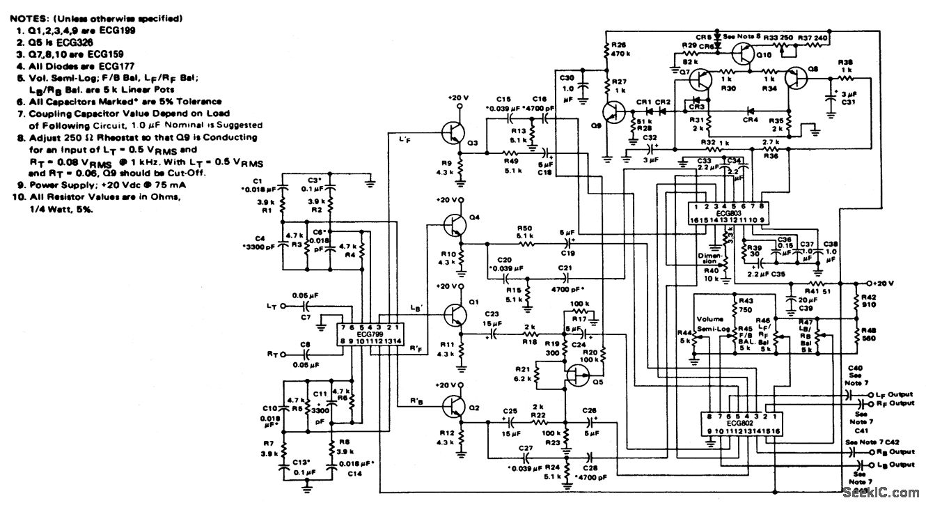
4-channel SQ logic decoder with a current drain of 75 mA at 20 volts. The input impedance is 2M ohms, and the output impedance is 2K ohms (courtesy of GTE Sylvania Incorporated). The 4-channel SQ logic decoder is an integrated...
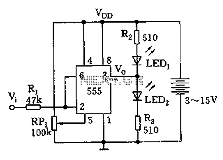
Figure 555 illustrates a simple logic circuit test lead. The test pen utilizes the 555 timer IC as its core component, incorporating a Schmitt trigger to assess the logic state of digital circuits. The circuit has two outputs: when...
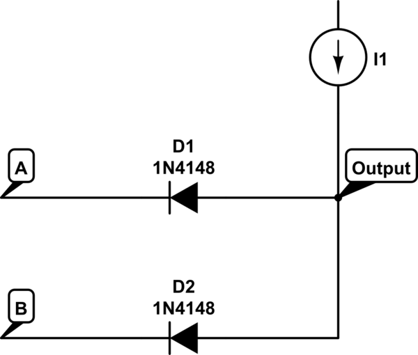
The voltage at the anode and cathode of the diodes is checked to determine whether they are conducting. There is confusion regarding the current source and how to determine the state of the diodes for input combinations (00, 01,...
This mini logic analyzer is a tool that allows users to observe the logic transitions (0 or 1) of a digital data signal on an LCD display. Such digital data signals can be found on the output pin of...
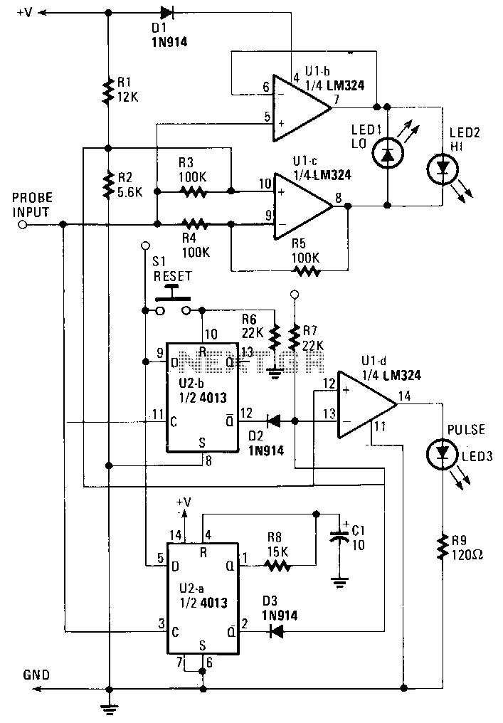
The probe operates using the power supply from the circuit under test (CUT). The input at the probe tip is divided into two pathways. One pathway directs the signal to the clock inputs of U2a and U2b. The other...