
Audio mV Meter

The Audio Millivolt Meter circuit is constructed to facilitate the measurement of low-level audio signals with high accuracy. The input stage incorporates a four-step attenuator that allows the user to select between four different voltage ranges, namely 10mV, 100mV, 1V, and 10V. This feature is crucial for accommodating a variety of signal levels encountered in audio applications.
The gain stage is designed to amplify the attenuated signal before it is further processed. Given the characteristics of the operational amplifier (op-amp) used in this design, two gain stages are implemented to ensure that the required bandwidth is achieved while maintaining stability at high gain levels. The gain of the overall circuit is determined to be 187.5, allowing for effective amplification from the basic sensitivity of 10mV to the maximum output of 1.875V.
The output from the gain stage drives a full-wave rectifier, which converts the AC signal into a DC signal suitable for driving the moving coil meter. The rectification process is essential for providing a readable output on the meter, which is calibrated to display full scale at 100µA with a resistance of 3.75K ohms. The design incorporates diodes in the feedback loop to manage the operational characteristics of the op-amp, ensuring that the gain is appropriately reduced when a signal is present.
Powering the circuit is achieved through two 9V PP3 batteries, which provide a nominal supply voltage of ±8V. This configuration permits a maximum output swing of ±7V, resulting in a peak-to-peak voltage of 14V. This output swing is critical for ensuring that the meter can accurately reflect the input signal levels, with the design accounting for diode voltage drops that impact the effective swing across the meter.
The selection of the feedback resistor, Rf, is pivotal in maintaining the op-amp's output swing within operational limits. By choosing a value of 15K ohms, the design ensures that the op-amp does not operate at its maximum output, allowing for a margin of safety and stability in the overall circuit performance.
In conclusion, the Audio Millivolt Meter is a sophisticated tool for measuring small audio signals, with a well-structured circuit that emphasizes precision, versatility, and reliability in audio signal measurement applications.This was my first AS Electronics project which I built way back in 1998! The original report, with diagrams, is shown here and a PDF version of the report is available for download. There are many occasions where I need to be able to measure small audio signals from various pieces of equipment and circuits.
A millivolt meter would be very handy on these occasions and therefore my project is an Audio Millivolt Meter. I have looked at two articles in electronics magazines (2, 3) for distortion meters which feature mV meters, and I have also looked at a millivolt meter circuit in an Op-Amp book (2). The designs are all basically the same. They consist of the following stages: The four step attenuator at the input of the circuit gives the meter its four ranges of 10mV, 100mV, 1V and 10V.
The gain stage amplifies the output signal from the attenuator. This is then amplified again by the meter drive stage. The output drives a full wave rectifier which drives the moving coil meter. Two gain stages are required due to the gain-bandwidth product of the op-amp. The attenuator stage of the meter gives it its ranges of 10mV, 100mV, 1V and 10V. A capacitor is connected in series with the input to stop any D. C. The basic sensitivity of the meter is 10mV, so the attenuator attenuates the input voltage for full scale for each of the range to 10mV. The input impedance of the meter is 100K © so: Figure 3 shows the meter drive circuit. The diodes rectify the A. C output from the op-amp. With no signal at the input to the op-amp, there is no output signal and so the diodes are turned off` (i.
e. not forward biased). This effectively means that the feedback loop of the op-amp is open circuit and so the op-amp will deliver its full gain of the 10 x 1012. This is the typical gain for the op-amp that I am using. When an input signal is applied, the output increases very rapidly until it reaches about 0. 7V when the diodes are forward biased. The feedback loop is now effectively complete, reducing the gain of the op-amp. The output voltage from the attenuator needed for the meter to read full scale is 10mV. The meter has a resistance of 3. 75K © and needs 100 µA to make it read full scale. Therefore, the voltage required to make the meter read full scale is: The circuit is powered from two 9V PP3 batteries.
Allowing for discharge after some use, the supply voltage could be ±8V. I have assumed that the maximum op-amp output swing must be at least 1V less than the supply rails as an op-amp cannot drive the output to the supply rail due to voltage drops across its internal drive circuit. This gives a maximum output swing of ±7V which is 14V pk-pk. 14V G· 2 = 7V peak. 7V X 0. 7071 = 4. 95V rms. On any half cycle only two diodes in the feedback loop will be forward biased and will appear in series with the meter.
These two diodes produce a 1. 2V offset, so the maximum swing available across the meter is 4. 95V 1. 2V = 3. 75V rms. Rf is included to in order to allow for the op-amp to be operated with a reasonably large output swing and to allow for sensibly sized resistors in the gain setting. Since 0. 375V is dropped across the meter: Rf could be a maximum of 30K © but this will make the op-amp`s output swing be 1V less than the supply rail and only just cause the meter to read full scale.
To make sure that the op-amp is not delivering its full output to just make the meter read full scale a value half way will be used, so making Rf 15K © will allow a wide margin. The calculation above shows the output from the op-amp taking into account the 3. 75K meter and the 15K feedback resistor. The total AC output voltage is 1. 875V. The basic sensitivity of the meter is 10mV, so the overall gain required to get from 10mV to 1. 875V is: 1. 875V/0. 01V = 187. 5. Two gain stages are required as one gain stage would not give the required bandwidth at that high gain.
At least two gain stages are required. 🔗 External reference
Related Circuits
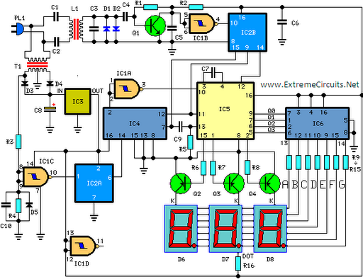
This circuit is designed for precise measurement of temperature in degrees Celsius. It features a transmitter section that converts the output voltage from a temperature sensor, which is proportional to the temperature being measured, into frequency. The resulting frequency...
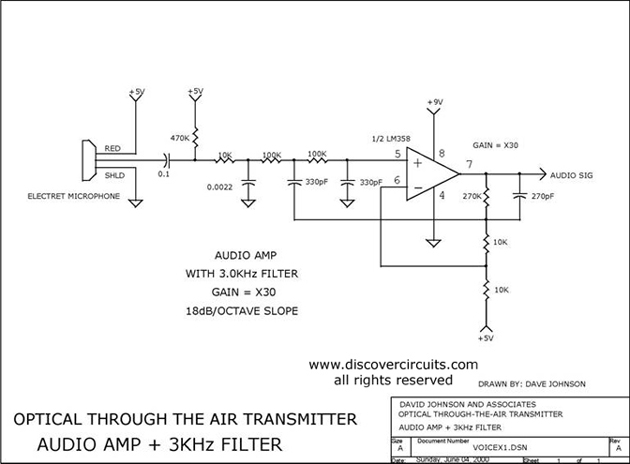
Audio amplifier with a 3 kHz filter. This circuit serves as the audio amplification section for a complete optical transmitter. It amplifies and filters voice audio signals from an electret microphone. The audio amplifier circuit is designed to enhance the...
Temperature sensor converter designed for use with a digital multimeter, capable of measuring temperatures from -40 °C to 110 °C. It features a state indicator and requires no calibration, utilizing the LM35 integrated circuit. The freezing point of water...
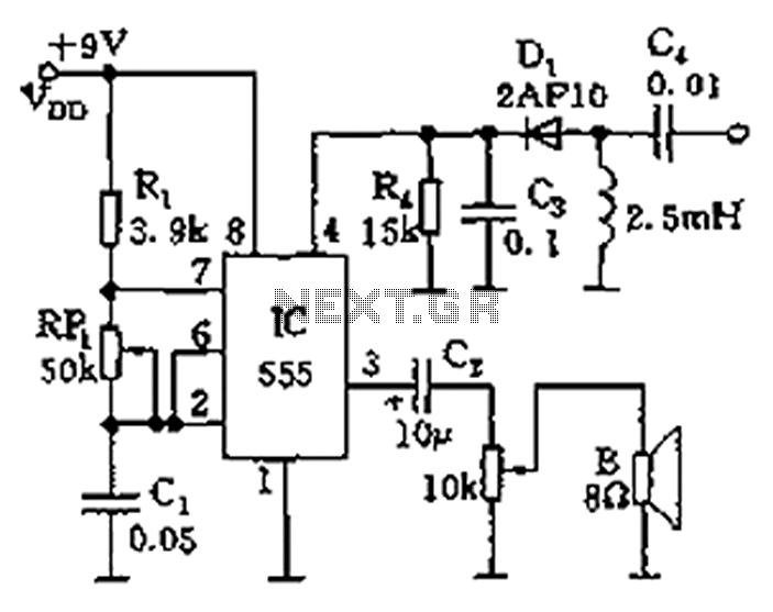
The circuit features a 555 timer integrated circuit along with components R1, RP1, C1, and others, which together form an audio oscillator. The frequency of the oscillator is determined by the formula f = 1.44 / ((R1 + 2...
The circuit utilizes two quad voltage comparators (LM339) to illuminate a series of eight LEDs that indicate volume levels. Each of the eight comparators is set to specific bias voltages determined by a voltage divider, allowing the lower right...
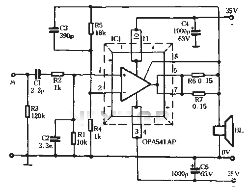
The Burr-Brown OPA541 chip is a power amplifier capable of operating with a maximum power supply voltage of 40V, delivering a continuous output current of up to 5A. The output current can be adjusted using an external resistor to...