
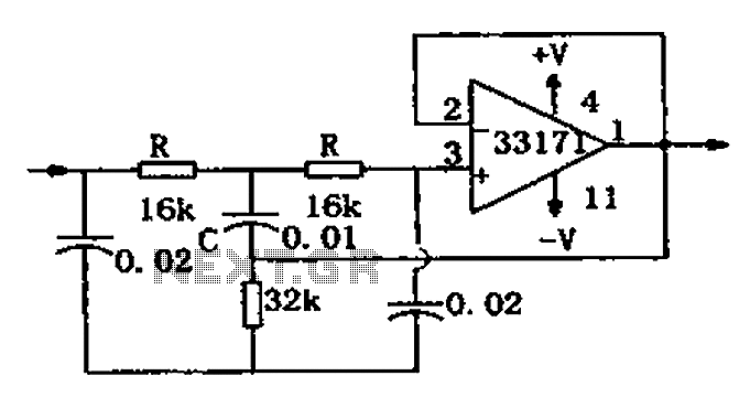
Notch filter circuit diagram MC33171
The trap circuit is designed to selectively filter out specific frequencies from a signal while allowing other frequencies to pass through. The MC33171 operational amplifier serves as the core component due to its excellent performance characteristics, including a high slew rate and low noise, which are essential for maintaining signal integrity in high-frequency applications.
In this circuit, the notch frequency can be adjusted by varying the values of the capacitor C and the resistors R. The formula for the notch frequency, f = 1/(4RC), indicates that the frequency response of the circuit is inversely proportional to the product of the resistance and capacitance values. Therefore, increasing the capacitance or resistance will lower the notch frequency, while decreasing these values will raise it.
The design typically consists of a feedback loop that incorporates the operational amplifier, capacitor, and resistors. The configuration ensures that the desired frequency is attenuated while minimizing the impact on adjacent frequencies. The high-performance characteristics of the MC33171 allow for precise tuning and effective filtering, making this trap circuit suitable for applications in audio processing, communication systems, and signal conditioning.
Overall, this trap circuit exemplifies the application of operational amplifiers in electronic filtering, demonstrating how component selection and configuration can be leveraged to achieve specific signal processing goals. As shown for the trap circuit. The circuit uses a high-performance op amp device MC33171 constitute trap. The device has a wide band and a high conversion rate. In the illustra ted component values by changing the value of a capacitor C and two resistors R, and other available notch frequency, its value is: f 1/4 RC.
Related Circuits
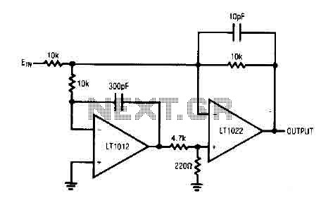
The circuit comprises a low drift LT1012 device and a high-speed amplifier LT1022. It functions as a unity gain inverter, with the summing node located at the junction of three 10k ohm resistors. The circuit monitors the summing node...
The receiver circuit in Figure 1 activates an audio alarm when the transmitter (Figure 2) moves beyond a specified perimeter. The transmitter functions as a voltage-controlled oscillator, operating at approximately 915 MHz within the unlicensed ISM (industrial/scientific/medical) band. It...
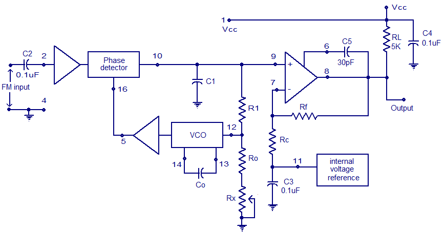
A simple PLL FM demodulator circuit using the IC XR2212 is presented. The XR2212 is a highly stable, monolithic PLL (phase-locked loop) IC specifically designed for communication and control system applications. It operates within a frequency range of 0.01...
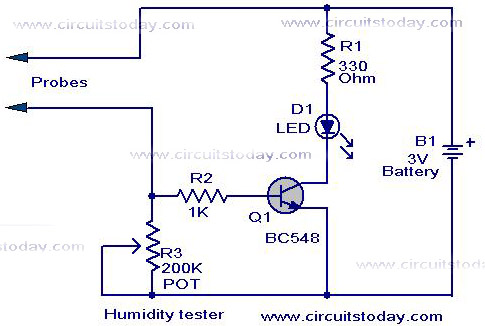
A simple humidity tester circuit using only an LED, a transistor, and a few resistors is explained with a clear circuit schematic. The humidity tester circuit is designed to provide a visual indication of humidity levels using basic electronic components....
While developing an infrared (IR) extender circuit, a method was needed to measure the relative intensities of different infrared light sources. This circuit utilizes an SFH2030 photodiode as the infrared sensor. A CA3140 MOSFET operational amplifier is employed in...
Circuit stereo TDA2822 audio power amplifier circuit schematics. In this series, the TDA2822M IC is utilized as the primary amplifier. Additionally, alternatives such as KA2209 and NJM2073 can also be employed. The TDA2822 audio power amplifier circuit is designed to...