
Voltage controlled amplifier
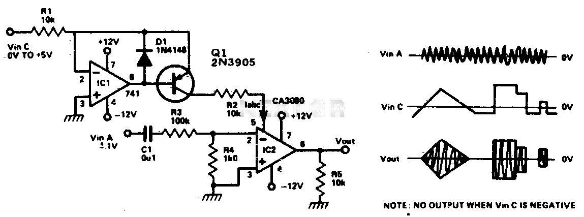
The operational amplifier circuit described operates as a differential amplifier, where the input signals are applied to the inverting (pin 2) and non-inverting (pin 3) terminals. The differential voltage of ±10 mV indicates that the circuit is designed for high precision, allowing it to amplify small voltage differences effectively. The additional input at pin 5 serves as a control mechanism, where the injected current (Iabc) modulates the gain of the amplifier. This feature is particularly useful in applications requiring dynamic adjustment of gain based on varying input conditions.
The output signal at pin 6 is a function of the differential input voltage and the gain set by the current at pin 5. This relationship can be expressed mathematically as V_out = Gain × V_diff, where V_diff is the voltage difference between pins 2 and 3. The linear control of gain ensures that the output signal remains proportional to the input, which is crucial for maintaining signal integrity, especially in audio applications.
Inserting an audio signal into this circuit allows for the amplification of audio frequencies, making it suitable for various applications such as audio processing, signal conditioning, and other electronic systems where precise signal amplification is required. The design ensures minimal distortion and high fidelity in the output, which is essential for high-quality audio performance.This circuit is basically an op amp with an nal (±10 mV) between pin 2 and 3 and by extra input at pin 5. A current Iabc is injected controlling the current on pin 5, the level of the into this input and this controls the gain of the signal output (pin 6) is controlled, device linerly
Thus by inserting an audio sig-. 🔗 External reference
Related Circuits
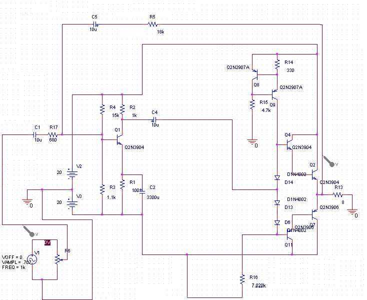
A 15 watt amplifier made using discrete components. Sergio designed this circuit for his Electronics Level II course. More: This amplifier uses a dual 20 Volt power supply and delivers 15 watts RMS into an 8 ohm load. Q1...
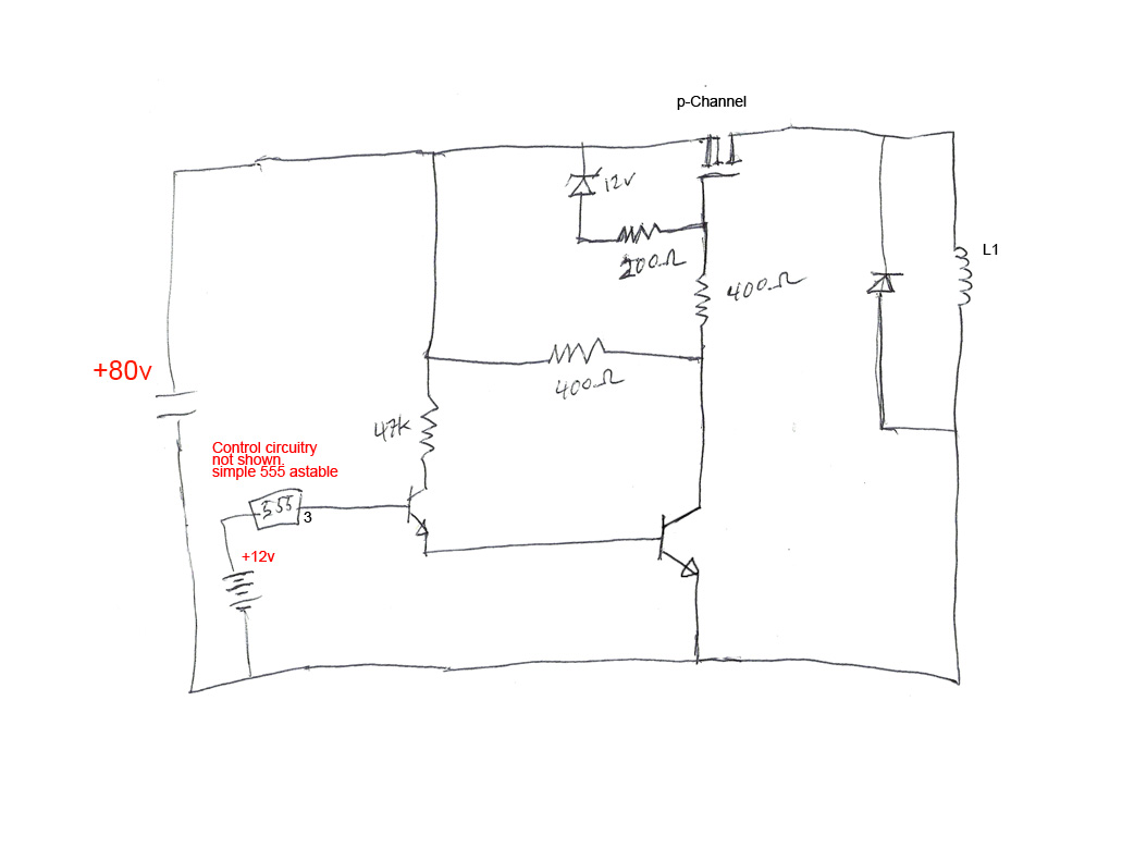
The circuit's premise involves powering an L1 coil with square pulses. A freewheeling diode is included to manage the back EMF field collapse, thereby protecting the circuitry. Previous experiments indicated that using an N-channel MOSFET on the high side...
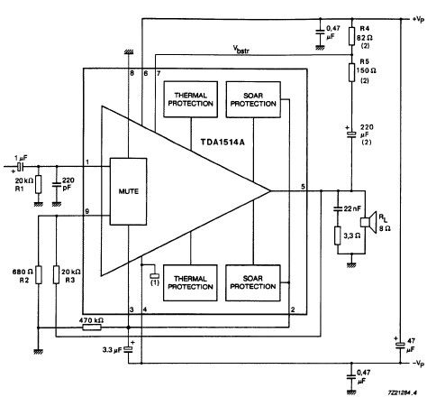
The TDA1514 audio amplifier circuit design is an electronic project capable of delivering high audio power output using a specialized audio integrated circuit (IC) and a few common components. Manufactured by Philips Semiconductor, the TDA1514 audio IC can provide...
This simple circuit is a good solution to the powering a dual supply op amp from a single battery problem. The circuit simply takes a positive voltage and inverts it. It uses only one 555 timer and a few...

The genesis for this hybrid electrostatic headphone amplifier occurred when I was in Hawaii on vacation, at a fancy hotel on Maui. Sitting at the bar on the beach, drinking "Blue Hawaiis," I drew the schematic for the amp...
Blue VALUES replaced by values in RED. Blue COMPONENTS removed from circuit. Red components added to circuit. More: Optional: move relay mute contacts to other side of C21. The provided description indicates modifications to an existing electronic circuit. The changes...